ESP-32 Fast Memory Copy
This article demonstrates how to copy memory fast on Xtensa (ESP-32). It analyzes the Xtensa CPU architecture, the memory layout, and instruction support. Benchmarking shows the custom fast copy routine for aligned data copy in Assembly is about 10% faster than stdlib provided in ROM.
ESP-32, ESP-IDF, Xtensa, Memory, RAM, ROM, Flash, Cache, ISA, Instruction Set Architecture, memcpy, Alignment, Benchmarking
--by Captdam @ Oct 13, 2026Index
I am recently working on a ESP-32 project that serves static files via HTTP using bare TCP. That means, the server does one job, copy data from flash or RAM to TCP buffer.
In my previous articles, ESP-32 TCP Baremetal HTTP server and String Comparison Micro-optimization on X86, ARM and Xtensa, I had discussed how to build a simple ESP-32 HTTP server based on TCP and how to micro-optimization for string operation on different CPU architectures. You may want to have a look into these two articles because it includes some basic knowledge that I am gonna use in this article.
In this article, I will discuss how to move data efficiently on Extensa (the CPU used inside ESP-32). More specifically:
-
How fast is the standard
memcpy()function provided in the ROM, and its limitations. -
What instructions on Xtensa platform can be used to move data.
-
Make a custom
memcpy()function in assembly language that works for 4-byte aligned data which runs faster than the standardmemcpy()function provided in the ROM.
In this article, we will be referring two documents:
-
Xtensa® Instruction Set Architecture (ISA) Summary by Cadence Design Systems. Xtensa is a customizable CPU IP core. This document provides information about the CPU architecture and instructions and registers we can use.
-
ESP32 TRM (Version 5.8) (ESP32 Technical Reference Manual Version 5.8) by Espressif Systems. ESP-32 implements the Xtensa CPU with other peripherals.
Memory Model
Harvard Architecture
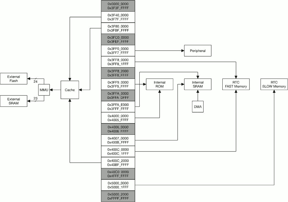
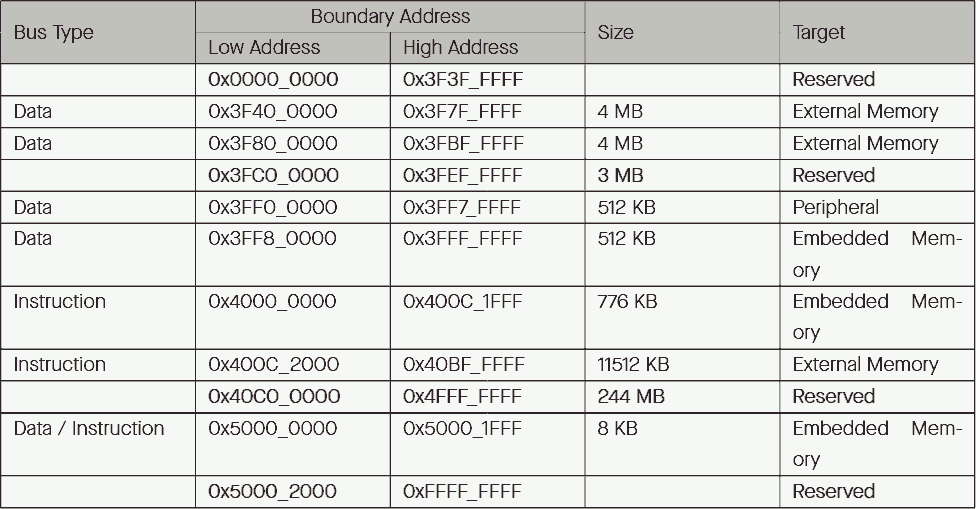
Xtensa is a dual-core Harvard architecture CPU with 32-bit address space. This means, two separate memory buses are used for data and instructions. The ESP-32 document states:
-
Addresses below
0x4000_0000are serviced using the data bus. -
Addresses in the range
0x4000_0000 ~ 0x4FFF_FFFFare serviced using the instruction bus. -
Addresses over and including
0x5000_0000are shared by the data and instruction bus.
Violating the instruction / data access pattern results in CPU panic. The program will halt.
Although the address of the memory bus is 32-bit wide, allowing 4GB of space, some regions are reserved (not connected), some regions are mapped to the same physical memory.
For example, the figure shows that the internal SRAM is mapped to both data memory space at address 0x3FFAE000 to 0x3FFFFFFF and instruction memory space at address 0x40070000 to 0x400BFFFF.
This allows us to store data in instruction space. When a program is initialized, the program text (including program instructions and initialized data) can be loaded as a whole unit into a SRAM region that is mapped to both instruction space (for instruction fetch) and data space (for data read and write). Otherwise, we have to load the instruction and data separately into instruction space and data space.
Memory Types
ESP-32 comes with different types of physical memories.
RAM
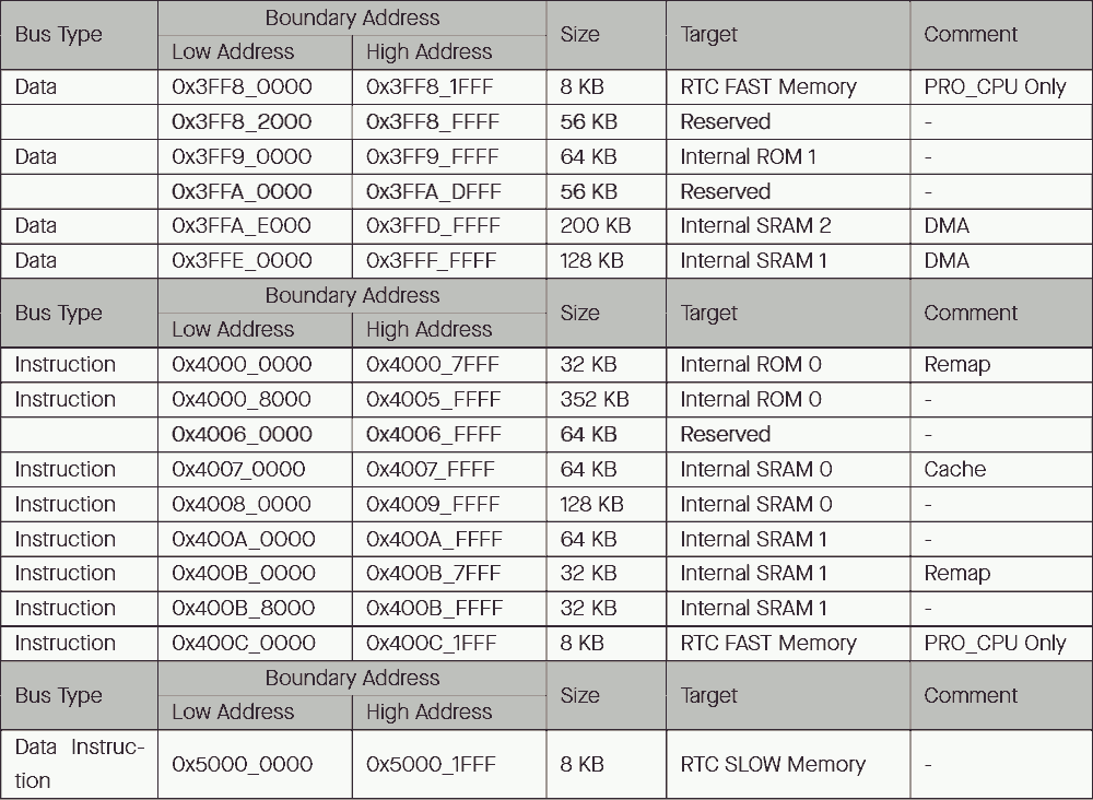
RAM, more specifically, internal SRAM. This is our main memory. This memory is directly connected to the CPU's memory bus. Any run-time data, including heap and stack, global (static) variables are stored in RAM. The program must be loaded from flash (or any other external device) into the RAM before its instruction can be fetched and executed by the CPU, and its data can be read or written by the CPU.
Xtensa uses Harvard architecture. The entire RAM is mapped to the data space, but only a portion of the RAM is mapped to the instruction space. The program instruction and the data must be placed into the dedicated memory region and follow the correct access pattern. Otherwise, the CPU will panic.
The RAM can be divided into 3 portions:
-
RAM0 is 192kB and can only be accessed in the instruction space.
-
RAM1 is 128kB and can be accessed in both instruction space and data space, but with word-wide reverse order.
-
RAM2 is 200kB and can be accessed in both instruction space and data space, in the same order.
Access (read, write, fetch) to RAM takes only one CPU cycle, unless stalled.
RAM is made from static RAM, or SRAM. This is an electrical engineering term, meaning it is made from static electronic D-type registers. No capacitor refresh need, as opposed to DRAM. Don't be confused with programming language term for static variable.
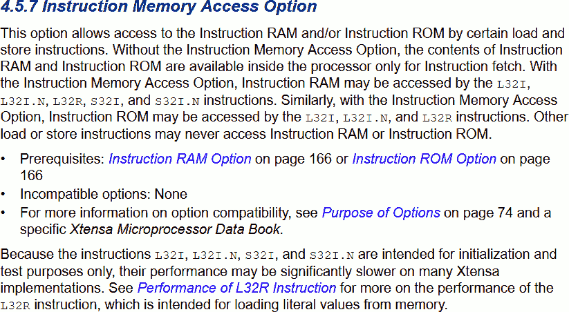
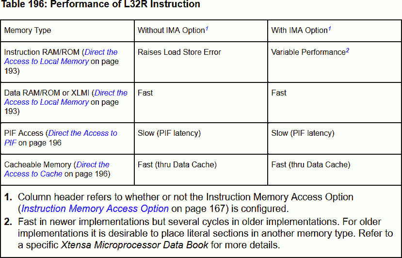
l32 Instruction - Xtensa ISA screenshotThe Xtensa document says: Only the loads L32I, L32I.N, and L32R can access InstRAM and InstROM locations and Only the stores S32I and S32I.N can access InstRAM.
We have to use l32 instruction to access instruction space. Furthermore, it is slower to access instruction space than data space. I cannot find the actual clock cycle to access instruction space and the reason of the slower speed, I guess it is because the instruction space is being accessed by the instruction fetch and data read at the same time, hence requires more cycles.
ROM
ROM is an internal read-only memory. As its name suggests, content is burned in the factory and we cannot modify it (unless you have 1 million dollars so you can order a custom batch). ROM provides 1st stage boot loader and some useful functions, including the standard C library, with memcpy().
The ROM can be divided into 2 portions:
-
ROM0 is 384kB and can only be accessed in the instruction space. The head 32kB can be remapped into RAM1 (mirrored in both instruction space and data space), allowing the head 32kB to be read like data.
-
ROM1 is 64kB and can only be accessed in the data space.
Access ROM takes only one CPU cycle, unless stalled.
Flash
Flash is where our program (including program instructions and initialized data) are stored. This memory is non-volatile, meaning its content remains the same after power off.
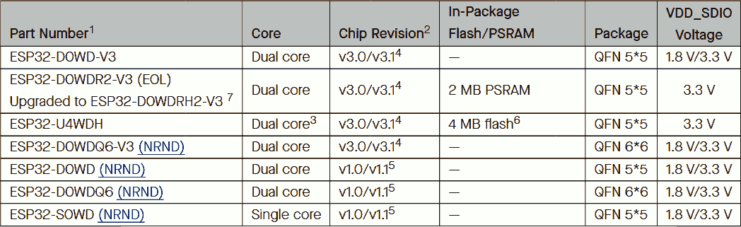

Flash can be external to the chip, connected to the chip via PCB (like ESP32-D0); or internal to the chip but external to the CPU wafer, connected to the CPU wafer via metal layers (like ESP32-PICO and ESP32-U4). Most importantly, flash is NOT DIRECTLY connected to the CPU's memory bus. The CPU cannot fetch instructions on flash, nor read or write data on flash.
ESP-32 supports up to 16MB of external memories (flash and RAM), which is sufficient to store a huge amount of instruction and data (for an embedded system), unless you want to store photos or movies (but who on earth does that, get an external SD card for it).
We can map:
into-
Address
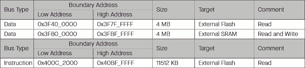
0x3F400000to0x3F7FFFFF(4MB) - External flash into data space for program text read. -
Address
0x3F800000to0x3FBFFFFF(4MB) - External RAM into data space for data read and write. -
Address
0x400C2000to0x40BFFFFF(11512kB) - External flash into instruction space for program execution.Address
0x40000000to0x400C1FFF(776kB) are used for internal ROM and RAM. Therefore, only 11512kB of space available.
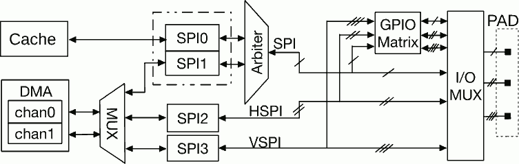
ESP-32 supports SPI (DSPI, QSPI) external memories. There are 4 SPI peripherals on ESP-32, SPI0 is used to access external memories.
Cache
Since flash and external RAM are not directly connected to the CPU's memory bus, the CPU cannot access them. One way is to manually load the content using SPI into the internal RAM, but this is low efficiently.
Cache system can be used to automatically perform the loading task in the background. The cache system maps parts of external SPI flash or external SPI RAM to its internal poll, by temporarily storing external content in an internal memory to allow access from internal devices. This allows the CPU to access external memory like it is internal.
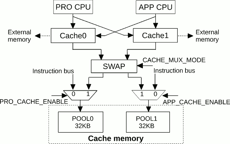
On ESP-32, there are two cache pools, each 32kB, made from 32 bytes long blocks.
Here is how it works. When the CPU wants something (read data or fetch instruction), it places the address on the memory bus. If that address belongs to an external device (for example, an instruction on flash), that request is routed to the cache system.
The cache system first checks if the required content is cached in the cache system's internal pool:
-
If yes, that's a cache hit, the content in the pool is returned to the CPU immediately, in one CPU cycle, unless stalled.
-
If not, that's a cache miss. The cache system must read from the external device first, replace the content into the pool, then the (updated) content in the pool is returned to the CPU. Execution of the current instruction is stalled while reading external device.
Data Allocation
Cache
It is fine to run programs on external flash, read data from external flash or external RAM. The cache system allows the CPU to access external memory like it is internal.
However, the cache pool is limited. It holds only two 32kB blocks of program text or data. That means, it is impossible to cache the entire external flash or external RAM. If the CPU tries to access some content from an external device that is not cached, an expensive cache miss happens.
For example, the CPU and RAM on ESP-32 is running at 160MHz, meaning accessing a 32-bit (a word) in-RAM or in-cache content takes only 1 clock cycle, or 6.25 nanoseconds. External Quad-SPI devices normally run at 40MHz (and if noisy or distance is long, the SPI clock frequency will be even lower), there will be 8 SPI cycles (4 bits per SPI cycle) to read a 32-bit content, or 200 nanoseconds. That is 32 times slower, not even considering other overheads like the SPI address phase.
Again, cache is limited. The content we just cached may be replaced by other content. When the same piece of content is required again but has been replaced, we must recache this content.
For less frequently used programs and data, or when the timing is not critical, it is OK to use cache. Cache miss is slow, other than that, cache is perfectly fine. Unless you are crazy with SPI clock noise or power consumption.
RAM
We can force some programs and data into the RAM. Therefore, access is always single cycle.
To do so, in C language with ESP-IDF, add the attribute IRAM_ATTR for program and constant data, DRAM_ATTR for data. Note, Xtensa uses Harvard architecture, IRAM_ATTR places content in Instruction memory, DRAM_ATTR places content in data memory:
DRAM_ATTR int globalStaticData_inDataRAM;

IRAM_ATTR int function_in() {

	IRAM_ATTR const static int localStaticData_inInstRAM = 1;
	DRAM_ATTR const static int localStaticData_inDataRAM = 2;

	int localData_inStack = 3; // Stack is always in RAM
	const static int localConstData_inTextFlash = 4;
}
During the program initialization, the in-RAM program and data will be copied from flash into RAM before invoke our main program.
However, RAM is limited. You cannot place all program text into RAM, only those frequently used or timing critical text should. For thoses not placed into RAM, we will let the cache system to load them on-the-fly. The cost is occasional stall for cache miss.
RAM is made from 32kB banks, accessing the same bank simultaneously from different upstream device will stall.
Benchmark Setup
In this article, we will write a simple program that copies data from one place (the source) to another (the destination):
#define MAXSIZE 2048

size_t len = 1024;
char dest[MAXSIZE];
char src[MAXSIZE];
memcpy(dest, src, len);
On a 32-bit platform, it is uncommon to see the compiler place variables on misaligned addresses. Aligned memory increases performance because it allows aligned multi-byte access. We can also add __attribute__((aligned(size))) attribute to ensure alignment.
char __attribute__((aligned(4))) dest[MAXSIZE];
char __attribute__((aligned(4))) src[MAXSIZE];
We will measure the CPU cycles between the start and end of the memory copy using the CPU cycle counter. To do so, we can use the uint32_t cpu_hal_get_cycle_count() macro provided by ESP-IDF, or directly read the CPU special register rsr.ccount ax in Assembly language.
#include "hal/cpu_hal.h"

uint32_t start = cpu_hal_get_cycle_count();
memcpy(dest, src, len);
uint32_t end = cpu_hal_get_cycle_count();
To print the cycle count in console:
#include "esp_log.h"

ESP_LOGI("[Copy]", "%x <-- %x", dest, src);
ESP_LOGI("[Copy]", "Cycles %d: %d", i, end - start);
To prevent program cache miss, eliminating any stall cycle contributed by the program instruction instead of the actual data to copy, we will place the program instruction into the RAM.
#include "esp_attr.h"

IRAM_ATTR app_main() {

}
The destination is always in RAM:
-
Data RAM (Static): As a static variable, if declared as
staticor declared out of function body. -
Data RAM (Stack): If declared in function body.
-
Instruction RAM: It is uncommon to write to instruction RAM, except loading program text into RAM.
The source can be placed in different memory locations:
-
Data RAM (Static): As a static variable, if declared as
staticor declared out of function body. -
Data RAM (Stack): If declared in function body.
-
Instruction RAM: If we are low on data RAM space, we can place data in instruction RAM. However, since Xtensa uses Harvard architecture, there is a limitation on instruction RAM access.
-
Flash: Can hold large data, but a cache miss can stall the process.
Now, put everything together:
#include "esp_log.h"
#include "esp_attr.h"
#include "hal/cpu_hal.h"

#include <string.h>

#define MAXSIZE 2048
#define LEN 1

DRAM_ATTR char __attribute__((aligned(4))) dest[MAXSIZE]; // Data RAM, static

IRAM_ATTR void app_main(void) {
	char __attribute__((aligned(4))) src[MAXSIZE]; // Data RAM, stack
//	const static char __attribute__((aligned(4))) src[MAXSIZE]; // Flash via cache
//	DRAM_ATTR const static char __attribute__((aligned(4))) src[MAXSIZE]; // Data RAM, static
//	IRAM_ATTR const static char __attribute__((aligned(4))) src[MAXSIZE]; // Instruction RAM

	ESP_LOGI("[Copy]", "%x <-- %x", dest, src);

	for (int i = 0; i < 5; i++) {
		uint32_t start = cpu_hal_get_cycle_count();

		memcpy(dest, src, LEN);

		uint32_t end = cpu_hal_get_cycle_count();
		ESP_LOGI("[Copy]", "Cycles %d: %d", i, end - start);
	}
}
In each case, we run for 5 times. The first run shows cycle count when the chache missed; hence, this count includes cycles to load content from external device. The following four runs show cycle count when cache hit.
Standard memcpy()
The on-chip ROM comes with a standard C library, including the memcpy() function. This function is placed in the ROM no matter if we used it or not, it is buried in the factory.
This function is stored at address 0x4000c2c8. For detail, you can disassemble the ROM ELF file tool/esp-rom-elfs/20240305/esp32_rev300_rom.elf.
I am not gonna walk through the disassembled machine code of this function. It is (somehow) optimized, for example, it copies 4 4-byte words at a time to reduce loop overhead.
You may choose to use or to not use this function. If you choose to use it, you don't need to write your own, which saves flash and instruction RAM space.
Benchmarking
Now, let's compile and load this program into ESP-32 for this benchmarking.
In all cases, since dest is declared as DRAM_ATTR as a global variable, its address is at 0x3FFB1E0C, which is in internal data memory space, target to internal SRAM2.
If the source is declared as const static, it will be placed in program text in flash:
const static char __attribute__((aligned(4))) src[MAXSIZE];
In this case, the address of src is at 0x3F403830, which is in external data space.
| Length | Run 1 | Run 2 | Run 3 | Run 4 | Run 5 |
|---|---|---|---|---|---|
| 1 | 673 | 40 | 40 | 40 | 40 |
| 4 | 675 | 42 | 42 | 42 | 42 |
| 70 | 1984 | 86 | 86 | 86 | 86 |
| 128 | 3274 | 113 | 113 | 113 | 113 |
| 1024 | 21530 | 673 | 673 | 673 | 673 |
| 2047 | 42407 | 1325 | 1325 | 1325 | 1325 |
| 2048 | 42394 | 1313 | 1313 | 1313 | 1313 |
If the source is declared without any attribute, it will be placed in the function stack, and stack can only be in data RAM:
char __attribute__((aligned(4))) src[MAXSIZE];
In this case, the address of src is at 0x3FFB43C0, which is in internal data space, target to internal SRAM2.
| Length | Run 1 | Run 2 | Run 3 | Run 4 | Run 5 |
|---|---|---|---|---|---|
| 1 | 39 | 39 | 39 | 39 | 39 |
| 4 | 41 | 41 | 41 | 41 | 41 |
| 70 | 85 | 85 | 85 | 85 | 85 |
| 128 | 112 | 112 | 112 | 112 | 112 |
| 1024 | 672 | 672 | 672 | 672 | 672 |
| 2047 | 1324 | 1324 | 1324 | 1324 | 1324 |
| 2048 | 1312 | 1312 | 1312 | 1312 | 1312 |
If the source is declared as DRAM_ATTR const static, it will be placed in data RAM:
DRAM_ATTR const static char __attribute__((aligned(4))) src[MAXSIZE];
In this case, the address of src is at 0x3FFB160C, which is in internal data space, target to internal SRAM2.
| Length | Run 1 | Run 2 | Run 3 | Run 4 | Run 5 |
|---|---|---|---|---|---|
| 1 | 39 | 39 | 39 | 39 | 39 |
| 4 | 41 | 41 | 41 | 41 | 41 |
| 70 | 85 | 85 | 85 | 85 | 85 |
| 128 | 112 | 112 | 112 | 112 | 112 |
| 1024 | 672 | 672 | 672 | 672 | 672 |
| 2047 | 1324 | 1324 | 1324 | 1324 | 1324 |
| 2048 | 1313 | 1313 | 1313 | 1313 | 1313 |
If the source is declared as IRAM_ATTR const static, it will be placed in instruction RAM:
IRAM_ATTR const static char __attribute__((aligned(4))) src[MAXSIZE];
In this case, the address of src is at 0x400835C8, which is in internal instruction space, target to internal SRAM0.
| Length | Run 1 | Run 2 | Run 3 | Run 4 | Run 5 |
|---|---|---|---|---|---|
| 1 | LoadStoreError | ||||
| 4 | 48 | 48 | 48 | 48 | 48 |
| 70 | LoadStoreError | ||||
| 128 | 337 | 337 | 337 | 337 | 337 |
| 1024 | 2465 | 2465 | 2465 | 2465 | 2465 |
| 2047 | LoadStoreError | ||||
| 2048 | 4897 | 4897 | 4897 | 4897 | 4897 |
Conclusion
| Length | 1 | 4 | 70 | 128 | 1024 | 2047 | 2048 | Speed (cycle/byte @ 2048B) |
|---|---|---|---|---|---|---|---|---|
| Flash (Miss) | 673 | 675 | 1984 | 3274 | 21530 | 42407 | 42394 | 20.700 |
| Flash (Hit) | 40 | 42 | 86 | 113 | 673 | 1325 | 1313 | 0.641 |
| Data RAM (Stack) | 39 | 41 | 85 | 112 | 672 | 1324 | 1312 | 0.641 |
| Data RAM (Static) | 39 | 41 | 85 | 112 | 672 | 1324 | 1313 | 0.641 |
| Instruction RAM | Error | 48 | Error | 337 | 2465 | Error | 4897 | 2.391 |
The result shows:
-
There are about 30+ cycles of overhead when using the stdlib
memcpy()function. It takes 40 cycles to read only 1 byte without any cache miss. When the read length grows, the average cycle per byte decreases. -
When reading from internal data RAM, the read speed is 0.64 cycles per byte.
-
When reading external memories (flash), the first read takes more cycles due to cache miss. It takes about 21 cycles to read a byte, that is more than 40 times slower than reading data RAM. Subsequent reads from flash consume a similar number of cycles as reading from internal data RAM.
-
When reading from instruction RAM, the read speed is 2.39 cycles per byte, that is about 4 times slower than reading data RAM. Furthermore, when the length is not a multiple of 4, the CPU panics, and throws a
LoadStoreError, which is becausememcpy()usesl8instructions for byte read andl16instructions for half-word read; however, instruction memory only allowsl32word read. -
It takes more cycles to read 2047 bytes than 2048 bytes. This is because
memcpy()will use multiple less-than-word reads and checks for the last 3 bytes when reading 2047 bytes, whereas all word read when reading 2048 bytes.
Our Fast Copy for Aligned Data
As I discussed in my previous article, multi-byte access on word-aligned data gives better permanence than byte access.
That means, if we can copy 4 bytes (or a word, since a word on a 32-bit CPU is 4 bytes) at a time, it will be 4 times faster than copying 1 byte a time:
for (int i = 0; i < len / 4; i++) {
	*((uint32_t*)dest) = *((uint32_t*)src);
	dest += 4;
	src += 4;
}
Although the address of the two buffers are aligned, the length may not. Therefore, we still need to use byte copy for the last 1 to 3 bytes:
for (int i = 0; i < len % 4; i++) {
	*((char*)dest) = *((char*)src);
	dest++;
	src++;
}
For example, to copy "Hello memories!", which contains 15 characters (excluding the zero-terminator), we will copy:
-
Hell- Word access -
o me- Word access -
mori- Word access -
e- Byte access -
s- Byte access -
!- Byte access
Let's compile our code:
400835c4 <mycopy>:
400835c4:	004136        	entry	a1, 32
400835c7:	41b240        	srli	a11, a4, 2
400835ca:	fb9c      	beqz.n	a11, 400835ed <mycopy+0x29>
400835cc:	a0cb20        	addx4	a12, a11, a2
400835cf:	c08c20        	sub	a8, a12, a2
400835d2:	fcc882        	addi	a8, a8, -4
400835d5:	418280        	srli	a8, a8, 2
400835d8:	039d      	mov.n	a9, a3
400835da:	01c882        	addi	a8, a8, 1
400835dd:	078876        	loop	a8, 400835e8 <mycopy+0x24>
400835e0:	09a8      	l32i.n	a10, a9, 0
400835e2:	994b      	addi.n	a9, a9, 4
400835e4:	02a9      	s32i.n	a10, a2, 0
400835e6:	224b      	addi.n	a2, a2, 4
400835e8:	a03b30        	addx4	a3, a11, a3
400835eb:	0c2d      	mov.n	a2, a12
400835ed:	144040        	extui	a4, a4, 0, 2
400835f0:	d48c      	beqz.n	a4, 40083601 <mycopy+0x3d>
400835f2:	424a      	add.n	a4, a2, a4
400835f4:	000382        	l8ui	a8, a3, 0
400835f7:	331b      	addi.n	a3, a3, 1
400835f9:	004282        	s8i	a8, a2, 0
400835fc:	221b      	addi.n	a2, a2, 1
400835fe:	f29247        	bne	a2, a4, 400835f4 <mycopy+0x30>
40083601:	f01d      	retw.n0x33
To be honest, I cannot say I am satisfied with the generated code. I decided to write my own using inline assembly language.
Xtensa ISA
Before we start to create our assembly code, I want to highlight two instructions provided by Xtensa.
Loop
Xtensa provides a set of zero-overhead looping instructions: loop, loopnez and loopgtz:
my_loop:
	loopxxx, as, label_end
	inst1
	inst2
label_end:
	inst3
where:
-
as- Number of iterations:-
loop- Ifasis zero, loops for 232 iterations. -
loopnez- Ifasis zero, skip this loop. -
loopgtz- Ifasis less or equal to zero, skip this loop.
-
-
label_end- Address of the next instruction after the loop.
There are 3 special registers in the CPU:
-
LCOUNT- Number of iterations remain, assigned byas- 1. -
LBEG- Begin of the loop, which is the address of the instruction after the loop instruction. In this example,inst1. -
LEND- End of the loop, which is the address of the instruction after the last instruction of this loop. In this example,inst3.
The loopxxx instruction can be used to reduce the loop overhead if the number of iteration is known before the loop starts. Without it, we will have to use additional instructions to keep track of number of iteration and do compare and branch out:
my_loop:
	inst1
	inst2
	addi	as, as, -1
	bnez	as, my_loop
label_end:
	inst3
Note there is only one set of loop registers. Therefore, nested loop is not allowed if using loop instruction for bother inner and outer loop, calling subroutine inside loop is risky because the subroutine may use loop instruction.
Harvard Architecture
Xtensa uses Harvard architecture, access pattern differes between the instruction space and the data space.
-
Data space allows byte access, half-word (16-bit) access and word (32-bit) access.
-
Instruction space allows word (32-bit) access only.
To allow read from instruction space, we must modify our code for copying the last few byte:
uint32_t last = *((uint32_t*)src);
	For (int i = 0; i < len % 4; i++) {
		*((char*)dest) = last;
		dest++;
		last >> 8;
}
In this way, we will use word read to read a whole word (including a few more extra bytes) from the source, just to satisfy the access pattern in the instruction space.
We will read a few extra bytes if the source's length is not a multiple of 4. This is fine, reading extra bytes has no side effects.
Furthermore, memory is assigned to our program by page, and page size is always multiple of 4. Therefore, reading a few extra bytes still fall within the same page, and it will not trigger an out-of-bounds memory error.
We use byte write to the destination so we don't accidentally write to other data. If the destination is in the instruction space, length must be multiple of 4.
Our Code
Let's create the function that write the last few bytes:
#define faststr_memcpy(dest, src, len) _faststr_memcpy((uint8_t*)dest, (uint8_t*)src, (size_t)len)
IRAM_ATTR void _faststr_memcpy(uint8_t* dest, uint8_t* src, size_t len) {
	asm volatile (
		"l32i	%[src], %[src], 0\n\t"
		"loopnez	%[len], 1f\n\t"
		"s8i	%[src], %[dest], 0\n\t"
		"srli	%[src], %[src], 8\n\t"
		"addi	%[dest], %[dest], 1\n\t"
		"1:	\n\t"
	:
		[src] "+a" (src),
		[dest] "+a" (dest)
	:
		[len] "a" (len)
	:
		"memory"
	);
}
At the beginning:
-
dest- The address of the last word in the destination buffer. -
src- The address of the last word in the source buffer. -
len- Number of bytes to copy in the last word, can be 0 to 3.
First, the content of the last word is loaded into src. It may include extra data.
If len is non-zero, load the loop counter, which is the number of bytes to copy in the last word. In the loop:
-
Write the lower 8 bits in
src(content) todest(address). -
Shift
src(content) right for 8 bits, so the next bytes goes to the lower 8-bit location. -
Incrment
dest(address), so it points to the next byte in the destination.
At the end:
-
dest- The Address after the last byte in the destination. -
src- Clobbed. -
len- Not changed.
All three parameters are no longer required.
Now, the main portion that performs the word copy:
#define faststr_memcpy4(dest, src, len) _faststr_memcpy4((uint32_t*)dest, (uint32_t*)src, (size_t)len)
IRAM_ATTR void _faststr_memcpy4(uint32_t* dest, uint32_t* src, size_t len) {
	uint32_t next = len & 0b11;
	len /= 4;
	asm volatile (
		"loopnez	%[len], 1f\n\t"
		"l32i	%[len], %[src], 0\n\t"
		"s32i	%[len], %[dest], 0\n\t"
		"addi	%[src], %[src], 4\n\t"
		"addi	%[dest], %[dest], 4\n\t"
		"1:	\n\t"
	:
		[len] "+a" (len),
		[src] "+a" (src),
		[dest] "+a" (dest)
	:
	:
		"memory"
	);
	faststr_memcpy(dest, src, next);
}
At the beginning:
-
dest- The address of the destination buffer. -
src- The address of the source buffer. -
len- Number of bytes to copy.
First, find out:
-
next- Number of bytes to copy in the last word, can be 0 to 3. -
len- Number of words to copy.
If len is non-zero, load the loop counter, which is the number of words to copy. In the loop:
-
lenno longer required, use this register as scratch register. -
Read a word from
src(address) intolen(scratch content). -
Write a word from
len(scratch content) intodest(address). -
Incrment
src(address) anddest(address) for 4 (word size).
For every 4 bytes, we need 1 cycle to read, 1 cycle to write, and 2 cycles to increment the two pointers. In conclusion, that is 4 cycles for every 4 bytes, or 1 cycle per byte. Here, the overhead is 2 cycles to increase the 2 pointers.
At the end:
-
dest- The address of the last word of the destination buffer. -
src- The address of the last word of the source buffer. -
len- Clobbed.
dest and src can be feed to faststr_memcpy(dest, src, len).
To minimize the overhead contributed by the pointer increment, we can perform multiple word read and write with incrementing offset, and then perform a combined pointer increment at the end of each iteration:
#define faststr_memcpy48(dest, src, len) _faststr_memcpy48((uint32_t*)dest, (uint32_t*)src, (size_t)len)
IRAM_ATTR void _faststr_memcpy48(uint32_t* dest, uint32_t* src, size_t len) {
	uint32_t next = len & 0b11111;
	len /= 32;
	asm volatile (
		"loopnez	%[len], 1f\n\t"
		"l32i	%[len], %[src], 0\n\t"
		"s32i	%[len], %[dest], 0\n\t"
		"l32i	%[len], %[src], 4\n\t"
		"s32i	%[len], %[dest], 4\n\t"
		"l32i	%[len], %[src], 8\n\t"
		"s32i	%[len], %[dest], 8\n\t"
		"l32i	%[len], %[src], 12\n\t"
		"s32i	%[len], %[dest], 12\n\t"
		"l32i	%[len], %[src], 16\n\t"
		"s32i	%[len], %[dest], 16\n\t"
		"l32i	%[len], %[src], 20\n\t"
		"s32i	%[len], %[dest], 20\n\t"
		"l32i	%[len], %[src], 24\n\t"
		"s32i	%[len], %[dest], 24\n\t"
		"l32i	%[len], %[src], 28\n\t"
		"s32i	%[len], %[dest], 28\n\t"
		"addi	%[src], %[src], 32\n\t"
		"addi	%[dest], %[dest], 32\n\t"
		"1:	\n\t"
	:
		[len] "+a" (len),
		[src] "+a" (src),
		[dest] "+a" (dest)
	:
	:
		"memory"
	);
	faststr_memcpy4(dest, src, next);
}
I decided to choose 32 bytes for a burst, because the cache block is 32 bytes long.
Program text inside the loop cannot exceed 256 bytes.
At the beginning:
-
dest- The address of the destination buffer. -
src- The address of the source buffer. -
len- Number of bytes to copy.
First, find out:
-
next- Number of bytes to copy in the last burst, can be 0 to 31. -
len- Number of burst to copy.
If len is non-zero, load the loop counter, which is the number of burst to copy. In the loop:
-
lenno longer required, use this register as scratch register. -
Read a word from
src(address) intolen(scratch content). -
Write a word from
len(scratch content) intodest(address). -
Read a word from
src+ 4 (address) intolen(scratch content). -
Write a word from
len(scratch content) intodest+ 4 (address). -
Continue. Read and write for 32 (burst size) bytes in total.
-
Incrment
src(address) anddest(address) for 32.
For every 32 bytes, we need 8 cycle to read, 8 cycle to write, and 2 cycles to increment the two pointers. In conclusion, that is 18 cycles for every 32 bytes, or slight more than half cycle per byte.
At the end:
-
dest- The address of the last burst of the destination buffer. -
src- The address of the last burst of the source buffer. -
len- Clobbed.
dest and src can be feed to faststr_memcpy4(dest, src, len).
Benchmarking
Now, let's compile and load this program into ESP-32 for this benchmarking.
400835b8 <_faststr_memcpy48>:
400835b8:	004136        	entry	a1, 32
400835bb:	418540        	srli	a8, a4, 5
400835be:	259876        	loopnez	a8, 400835e7 <_faststr_memcpy48+0x2f>
400835c1:	0388      	l32i.n	a8, a3, 0
400835c3:	0289      	s32i.n	a8, a2, 0
400835c5:	1388      	l32i.n	a8, a3, 4
400835c7:	1289      	s32i.n	a8, a2, 4
400835c9:	2388      	l32i.n	a8, a3, 8
400835cb:	2289      	s32i.n	a8, a2, 8
400835cd:	3388      	l32i.n	a8, a3, 12
400835cf:	3289      	s32i.n	a8, a2, 12
400835d1:	4388      	l32i.n	a8, a3, 16
400835d3:	4289      	s32i.n	a8, a2, 16
400835d5:	5388      	l32i.n	a8, a3, 20
400835d7:	5289      	s32i.n	a8, a2, 20
400835d9:	6388      	l32i.n	a8, a3, 24
400835db:	6289      	s32i.n	a8, a2, 24
400835dd:	7388      	l32i.n	a8, a3, 28
400835df:	7289      	s32i.n	a8, a2, 28
400835e1:	20c332        	addi	a3, a3, 32
400835e4:	20c222        	addi	a2, a2, 32
400835e7:	248240        	extui	a8, a4, 2, 3
400835ea:	079876        	loopnez	a8, 400835f5 <_faststr_memcpy48+0x3d>
400835ed:	0388      	l32i.n	a8, a3, 0
400835ef:	0289      	s32i.n	a8, a2, 0
400835f1:	334b      	addi.n	a3, a3, 4
400835f3:	224b      	addi.n	a2, a2, 4
400835f5:	144040        	extui	a4, a4, 0, 2
400835f8:	0338      	l32i.n	a3, a3, 0
400835fa:	079476        	loopnez	a4, 40083605 <_faststr_memcpy48+0x4d>
400835fd:	004232        	s8i	a3, a2, 0
40083600:	413830        	srli	a3, a3, 8
40083603:	221b      	addi.n	a2, a2, 1
40083605:	f01d      	retw.n
Here is the machine code generated by the compiler, our code is placed at address 0x400835B8, which is in internal instruction memory space, target to internal SRAM0.
Furthermore, the compiler inlined the word copy subroutine _faststr_memcpy4 at address 0x400835EA and byte copy subroutine _faststr_memcpy at address 0x400835F8.
We will try both:
-
Word copy - Call
faststr_memcpy4(). -
Burst copy - Call
faststr_memcpy48(), which may invokefaststr_memcpy4()for last block.
In all cases, since dest is declared as DRAM_ATTR as a global variable, its address is at 0x3FFB1E0C. (Same as when using stdlib)
If the source is declared as const static, its address is at 0x3F403830, which is in external data space. (Same as when using stdlib)
| Length | Run 1 | Run 2 | Run 3 | Run 4 | Run 5 |
|---|---|---|---|---|---|
| 1 (burst) | 670 | 37 | 37 | 37 | 37 |
| 1 (word) | 653 | 21 | 21 | 21 | 21 |
| 4 (burst) | 672 | 39 | 39 | 39 | 39 |
| 4 (word) | 655 | 22 | 22 | 22 | 22 |
| 70 (burst) | 1970 | 69 | 69 | 69 | 69 |
| 70 (word) | 1981 | 84 | 84 | 84 | 84 |
| 128 (burst) | 3266 | 100 | 100 | 100 | 100 |
| 128 (word) | 3301 | 140 | 140 | 140 | 140 |
| 1024 (burst) | 21466 | 604 | 604 | 604 | 604 |
| 1024 (word) | 21894 | 1036 | 1036 | 1036 | 1036 |
| 2047 (burst) | 42282 | 1195 | 1195 | 1195 | 1195 |
| 2047 (word) | 43145 | 2063 | 2063 | 2063 | 2063 |
| 2048 (burst) | 42266 | 1180 | 1180 | 1180 | 1180 |
| 2048 (word) | 43142 | 2060 | 2060 | 2060 | 2060 |
If the source is declared without any attribute, its address is at 0x3FFB43C0, which is in internal data space, target to internal SRAM2. (Same as when using stdlib)
| Length | Run 1 | Run 2 | Run 3 | Run 4 | Run 5 |
|---|---|---|---|---|---|
| 1 (burst) | 37 | 37 | 37 | 37 | 37 |
| 1 (word) | 21 | 21 | 21 | 21 | 21 |
| 4 (burst) | 38 | 38 | 38 | 38 | 38 |
| 4 (word) | 22 | 22 | 22 | 22 | 22 |
| 70 (burst) | 68 | 68 | 68 | 68 | 68 |
| 70 (word) | 84 | 84 | 84 | 84 | 84 |
| 128 (burst) | 100 | 100 | 100 | 100 | 100 |
| 128 (word) | 140 | 140 | 140 | 140 | 140 |
| 1024 (burst) | 604 | 604 | 604 | 604 | 604 |
| 1024 (word) | 1036 | 1036 | 1036 | 1036 | 1036 |
| 2047 (burst) | 1195 | 1195 | 1195 | 1195 | 1195 |
| 2047 (word) | 2063 | 2063 | 2063 | 2063 | 2063 |
| 2048 (burst) | 1180 | 1180 | 1180 | 1180 | 1180 |
| 2048 (word) | 2060 | 2060 | 2060 | 2060 | 2060 |
If the source is declared as DRAM_ATTR const static, its address is at 0x3FFB160C, which is in internal data space, target to internal SRAM2. (Same as when using stdlib)
| Length | Run 1 | Run 2 | Run 3 | Run 4 | Run 5 |
|---|---|---|---|---|---|
| 1 (burst) | 37 | 37 | 37 | 37 | 37 |
| 1 (word) | 21 | 21 | 21 | 21 | 21 |
| 4 (burst) | 38 | 38 | 38 | 38 | 38 |
| 4 (word) | 22 | 22 | 22 | 22 | 22 |
| 70 (burst) | 68 | 68 | 68 | 68 | 68 |
| 70 (word) | 84 | 84 | 84 | 84 | 84 |
| 128 (burst) | 100 | 100 | 100 | 100 | 100 |
| 128 (word) | 140 | 140 | 140 | 140 | 140 |
| 1024 (burst) | 604 | 604 | 604 | 604 | 604 |
| 1024 (word) | 1036 | 1036 | 1036 | 1036 | 1036 |
| 2047 (burst) | 1195 | 1195 | 1195 | 1195 | 1195 |
| 2047 (word) | 2063 | 2063 | 2063 | 2063 | 2063 |
| 2048 (burst) | 1181 | 1181 | 1181 | 1181 | 1181 |
| 2048 (word) | 2060 | 2060 | 2060 | 2060 | 2060 |
If the source is declared as IRAM_ATTR const static, its address is at 0x40083608, which is in internal instruction space, target to internal SRAM0. (Different from when using stdlib, because adding our copy function in instruction RAM) Furthermore, it is placed just after our burst copy function.
| Length | Run 1 | Run 2 | Run 3 | Run 4 | Run 5 |
|---|---|---|---|---|---|
| 1 (burst) | 45 | 45 | 45 | 45 | 45 |
| 1 (word) | 29 | 29 | 29 | 29 | 29 |
| 4 (burst) | 53 | 53 | 53 | 53 | 53 |
| 4 (word) | 37 | 37 | 37 | 37 | 37 |
| 70 (burst) | 195 | 195 | 195 | 195 | 195 |
| 70 (word) | 211 | 211 | 211 | 211 | 211 |
| 128 (burst) | 331 | 331 | 331 | 331 | 331 |
| 128 (word) | 372 | 372 | 372 | 372 | 372 |
| 1024 (burst) | 2403 | 2403 | 2403 | 2403 | 2403 |
| 1024 (word) | 2836 | 2836 | 2836 | 2836 | 2836 |
| 2047 (burst) | 4779 | 4779 | 4779 | 4779 | 4779 |
| 2047 (word) | 5647 | 5647 | 5647 | 5647 | 5647 |
| 2048 (burst) | 4771 | 4771 | 4771 | 4771 | 4771 |
| 2048 (word) | 5652 | 5652 | 5652 | 5652 | 5652 |
Conclusion
| Length | 1 | 4 | 70 | 128 | 1024 | 2047 | 2048 | Speed (cycle/byte @ 2048B) |
|---|---|---|---|---|---|---|---|---|
| Flash (Miss) - Burst | 670 | 672 | 1970 | 3266 | 21466 | 42282 | 42266 | 20.638 |
| Flash (Miss) - Word | 653 | 655 | 1981 | 3301 | 21894 | 43145 | 43142 | 21.065 |
| Flash (Hit) - Burst | 37 | 39 | 69 | 100 | 604 | 1195 | 1180 | 0.576 |
| Flash (Hit) - Word | 21 | 22 | 84 | 140 | 1036 | 2063 | 2060 | 1.006 |
| Data RAM (Stack) - Burst | 37 | 38 | 68 | 100 | 604 | 1195 | 1180 | 0.576 |
| Data RAM (Stack) - Word | 21 | 22 | 84 | 140 | 1036 | 2063 | 2060 | 1.006 |
| Data RAM (Static) - Burst | 37 | 38 | 68 | 100 | 604 | 1195 | 1181 | 0.577 |
| Data RAM (Static) - Word | 21 | 22 | 84 | 140 | 1036 | 2063 | 2060 | 1.006 |
| Instruction RAM - Burst | 45 | 53 | 195 | 331 | 2403 | 4779 | 4771 | 2.330 |
| Instruction RAM - Word | 29 | 37 | 211 | 372 | 2836 | 5647 | 5652 | 2.760 |
The result shows:
-
There are about 30+ cycles of overhead when using the 32-byte burst copy
faststr_memcpy48()function, but only around 20 cycles of overhead when using the 4-byte word copyfaststr_memcpy4()function. Burst copy should be used for long content, word copy should be used for short copy. -
When reading from internal data RAM, the speed is 0.58 cycles per byte for burst copy, and 1.01 cycles per byte for word copy.
-
When reading external memories (flash), the first read takes more cycles due to cache miss. It takes about 21 cycles to read a byte, that is more than 40 times slower than reading data RAM. Subsequent reads from flash consume a similar number of cycles as reading from internal data RAM.
-
When reading from instruction RAM, the read speed is about 2.33 cycles per byte for burst copy and 2.76 cycles per byte for word copy, slower than reading data RAM.
-
It takes more cycles to read 2047 bytes than 2048 bytes. This is because our code must invoke the less-than-word reads for the last 3 bytes when reading 2047 bytes, whereas all word read when reading 2048 bytes.
Our Code vs stdlib
| Length | 1 | 4 | 70 | 128 | 1024 | 2047 | 2048 | Speed (cycle/byte @ 2048B) |
|---|---|---|---|---|---|---|---|---|
| Flash (Miss) - stdlib | 673 | 675 | 1984 | 3274 | 21530 | 42407 | 42394 | 20.700 (baseline) |
| Flash (Miss) - Burst | 670 | 672 | 1970 | 3266 | 21466 | 42282 | 42266 | 20.638 (+0.3%) |
| Flash (Miss) - Word | 653 | 655 | 1981 | 3301 | 21894 | 43145 | 43142 | 21.065 (-1.8%) |
| Flash (Hit) - stdlib | 40 | 42 | 86 | 113 | 673 | 1325 | 1313 | 0.641 (baseline) |
| Flash (Hit) - Burst | 37 | 39 | 69 | 100 | 604 | 1195 | 1180 | 0.576 (+10.1%) |
| Flash (Hit) - Word | 21 | 22 | 84 | 140 | 1036 | 2063 | 2060 | 1.006 (-56.9%) |
| Data RAM (Stack) - stdlib | 39 | 41 | 85 | 112 | 672 | 1324 | 1312 | 0.641 (baseline) |
| Data RAM (Stack) - Burst | 37 | 38 | 68 | 100 | 604 | 1195 | 1180 | 0.576 (+10.1%) |
| Data RAM (Stack) - Word | 21 | 22 | 84 | 140 | 1036 | 2063 | 2060 | 1.006 (-57.0%) |
| Data RAM (Static) - stdlib | 39 | 41 | 85 | 112 | 672 | 1324 | 1313 | 0.641 (baseline) |
| Data RAM (Static) - Burst | 37 | 38 | 68 | 100 | 604 | 1195 | 1181 | 0.577 (+10.1%) |
| Data RAM (Static) - Word | 21 | 22 | 84 | 140 | 1036 | 2063 | 2060 | 1.006 (-56.9%) |
| Instruction RAM - stdlib | Error | 48 | Error | 337 | 2465 | Error | 4897 | 2.391 (baseline) |
| Instruction RAM - Burst | 45 | 53 | 195 | 331 | 2403 | 4779 | 4771 | 2.330 (+2.6%) |
| Instruction RAM - Word | 29 | 37 | 211 | 372 | 2836 | 5647 | 5652 | 2.760 (-15.4%) |
Compare our code to the stdlib in ROM:
-
Our burst copy code is 10% faster than the stdlib when accessing data RAM or in cached flash.
-
Our burst copy code is slightly faster than the stdlib when accessing instruction RAM or in uncached flash.
-
Our word copy code is faster for short data.
-
Our code works when accessing instruction RAM.
, however:
-
The source and destination address must be 4-byte aligned in our code.
In terms of memories type:
-
Data RAM is always favoured.
-
Cached external memories shows the same performance as internal data RAM. However, cache can be replaced by other content; hence, its behavious is unpredictable.
-
Instruction RAM is 4 times slower than data RAM, and access pattern matters. However, instruction RAM is predictable.
Memory Congestion
ESP-32 comes with a dual-core CPU and DMAs. In other words, there are multiple masters (CPU cores and DMAs) accessing the memories at the same time.
The RAM is made from 32kB (0x8000) banks, each bank can only serve one master at a time. If multiple masters are accessing the same bank at the same time, the speed decreases.
To simulate a memory congestion, I will launch the second core and that core will continuously write the destination.
DRAM_ATTR char __attribute__((aligned(4))) dest[MAXSIZE];
IRAM_ATTR void spin(void* param) {
	uint32_t tmp;
	asm volatile (
		"1:	\n\t"
		"movi	%[tmp], -1\n\t"
		"loopnez	%[tmp], 2f\n\t"
		"s32i	%[tmp], %[dest], 0\n\t"
		"2:	\n\t"
		"j	1b\n\t"
	:
		[tmp] "=&a" (tmp)
	:
		[dest] "a" (dest)
	:
		"memory"
	);
}

IRAM_ATTR void app_main(void) {
	xTaskCreatePinnedToCore(spin, "Spin", 2048, NULL, 15, NULL, APP_CPU_NUM);
	vTaskDelay(1000 / portTICK_PERIOD_MS);

	/* Benchmarking */
}
The second core is executing spin. Inside it, a zero-overhead loop is used to access dest at a frequency of 1 access per cycle.
Furthermore, we will add a secondary destination dest2 that is aligned by 32kB and its size is 32kB. In this way, dest2 is stored in a dedicated bank.
DRAM_ATTR char __attribute__((aligned(32*1024))) dest2[32*1024];
We uses our 32-byte burst copy. In that function, for each 32 bytes, we perform 8 reads, 8 writes and 2 index increments. That is in 88% of the time, accessed at 0.5 writes per cycle and 0.5 reads per cycle.
Let's check the benchmarking:
The first core is executing _faststr_memcpy48, at address 0x40083740, its bank's address is 0x40080000. In another word, the first core fetches bank 0x40080000 at 1 fetch per cycle.
The second core is executing spin, at address 0x40082570, its bank's address is 0x40080000. In another word, the second core fetches bank 0x40080000 at 1 fetch per cycle. Frequency is 1 write per cycle.
The second core is writing dest, at address 0x3FFC0000, its bank's address is 0x3FFC0000.
| Case | Destination | Source | Run 1 | Run 2 | Run 3 | Run 4 | Run 5 | ||||
|---|---|---|---|---|---|---|---|---|---|---|---|
| 1 | dest | 0x3FFC0000 | +0000 | Flash | 0x3F400000 | +30D8 | 42269 | 1180 | 1180 | 1180 | 1180 |
| 2 | dest | 0x3FFC0000 | +0000 | D-RAM | 0x3FFC0000 | +2CE0 | 2069 | 2069 | 2069 | 2069 | 2069 |
| 3 | dest2 | 0x3FFB8000 | +0000 | D-RAM | 0x3FFC0000 | +2CE0 | 1181 | 1181 | 1181 | 1181 | 1181 |
| 4 | dest | 0x3FFC0000 | +0000 | I-RAM | 0x40080000 | +3790 | 4771 | 4771 | 4771 | 4771 | 4771 |
The result is interesting:
-
The throughput is not affected: 2 cycles per word. When:
-
Bank
0x3FFC0000in data RAM - 1.5 access/cycle: 0.5 writes from core 1, 1 write from core 2. -
Flash
0x3F400000- 0.5 access/cycle: 0.5 reads from core 1. -
Bank
0x40080000in instruction RAM - 2 access/cycle: 1 fetch from core 1, 1 fetch from core 2.
-
-
The throughput is halved: 4 cycles per word. When:
-
Bank
0x3FFC0000in data RAM - 2 access/cycle: 0.5 reads from core 1, 0.5 writes from core 1, 1 write from core 2. -
Bank
0x40080000in instruction RAM - 2 access/cycle: 1 fetch from core 1, 1 fetch from core 2.
-
-
The throughput is not affected: 2 cycles per word. When:
-
Bank
0x3FFC0000in data RAM - 1.5 access/cycle: 0.5 reads from core 1, 1 write from core 2. -
Bank
0x3FFB8000in data RAM - 0.5 access/cycle: 0.5 writes from core 1. -
Bank
0x40080000in instruction RAM - 2 access/cycle: 1 fetch from core 1, 1 fetch from core 2.
-
-
The throughput is not affected: 8 cycles per word. When:
-
Bank
0x3FFC0000in data RAM - 1.5 access/cycle: 0.5 writes from core 1, 1 write from core 2. -
Bank
0x40080000in instruction RAM - 2.5 access/cycle: 0.5 reads from core 1, 1 fetch from core 1, 1 fetch from core 2.
-
For data RAM, when the access rate hits 2, the throughput halved. For instruction RAM, probably because the speed is already low, or the CPU caches instruction, the throughput rate doesn't change when access rate hits 2.