Engineering drawing PDF & titleblock & index generator
Merge, add text, pictures and custom titleblock to PDF engineering drawing, and generate index.
PDF, Engineering drawing, titleblock, Web app
--by Captdam @ Sep 20, 2024- Also on GitHub: https://github.com/captdam/DrawingTitleblock
- Here is the English version of this article
- 这里是这篇文章的中文版
Index
Motivation
I am doing some mechanical design in my work and one of my duties is to create mechanical drawings for fabrication. I have been using SoldWorks and Fusion to create the drawings, they did a great job to design and render the models on drawing; however, they have limitations on creating titleblock.
The first CAD tool I used at work is SolidWorks. When creating a drawing package, I start by selecting a template file that contains the titleblock I need, followed by inserting assemblies and parts. SolidWorks provides some attributes that I can insert into the titleblock on each page, such as page number, page count, author. However, it has limitations:
- Page must start from 1. So, I cannot create a cover page with page number at 0.
- The update date of all pages will always be the modified date of the file. I always have each page of my drawing package containing a part or a subassembly of the design, and I would like the update date on that page to be the time I modify the part in that page. However, this is impossible.
- I cannot generate an index page; I have to manually create the index.
Later, the company switched to Fusion to reduce cost. It has a worse drawing editior, on addition of the limitation I had with SolidWorks, in Fusion:
- There is a very limited amount of attributes I can choose from to insert into the titleblock. I cannot make my custom attributes.
First attempt
After some searches about how to make the titleblock in Solidworks and in Fusion, I chose to stop investing in ways to make titleblock in these CADs; instead, I decided to write a program to help me making the titleblock myself.
I found a JS library PDF-Lib that allows me to manipulate PDF files. I can make a web app base on this lib that gives me benifits:
- Run on nearly any computer that has web browser. If that computer can run CADs, that computer can run web browser and this program.
- Easy to make GUI by utilizing HTML and CSS. And I am familiar with them because I write my website.
- No server, no upload, everything on client side. Makes confidentiality.
I will let the CADs export drawings without any titleblock (or only with limited information such as scale); then I will use the this program add titleblock and attributes to generate the final drawing packages.
My first program performs the following tasks:
- Import drawing PDF, two images for company logo and customer logo, and a CSV index file.
- For each page in the drawing PDF. First, use predefined rules (a set of SVG calls) to draw the titleblock template and logos. Then, extract attributes from the index file such as project name, part name, modify data, author. This information will be placed at a predefined location. In the end, insert an auto increment page number.
- Prepend a blank page, add titleblock template, logos and attributes. Then, add the project name and generate an index using predefined rules.
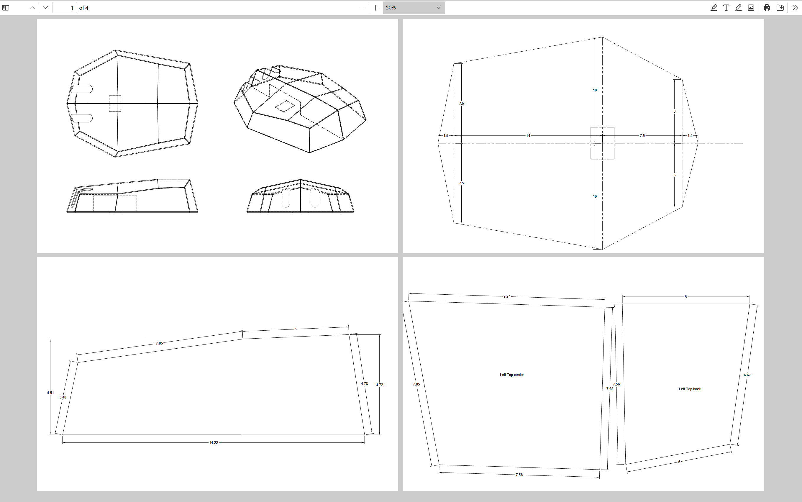
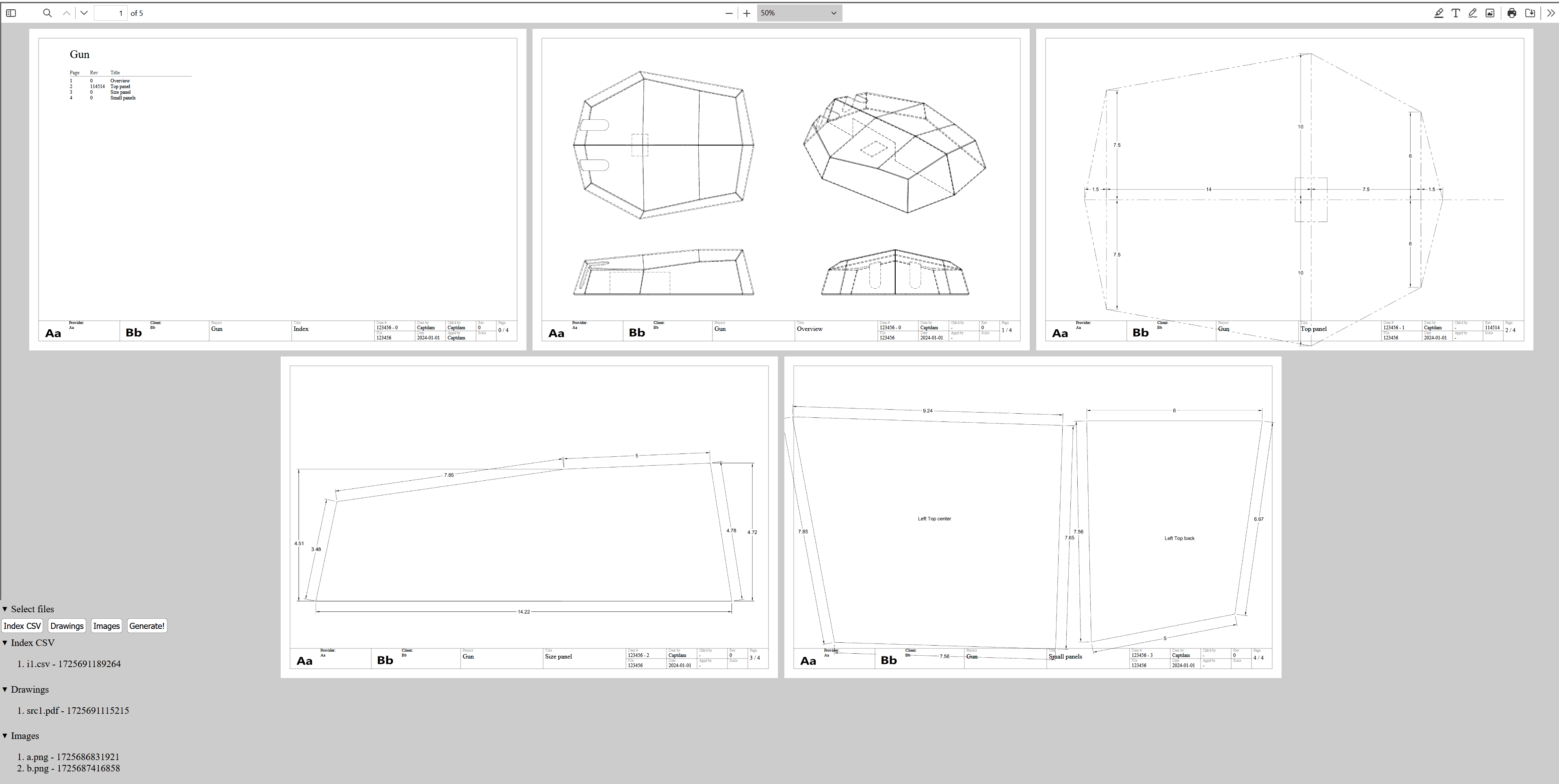
Following example shows a source drawing, the index file and the final drawing:

Second attempt
The first attempt works fine, but I cannot say it is an elegant solution. It has lots of limitations, the process is complex, the code is ugly. It hasn't solved some problems.
- It only supports a set of attributes and the positions to include these attributes are fixed. To add more attributes or to change the positions to place the attributes, I have to modify the code of this program.
- It accepts and only accepts two images, the company’s logo and the customer’s logo. We always have the company logo on our drawing; therefore, it makes no sense to select the first image every time. Furthermore, I would like to be able to insert more images for other purposes.
- It uses a set of SVG calls hardcoded in the program to draw the titleblock. It only supports one titleblock template and modifying it requires modifying the code of the program. I was first thinking about using SVG files; but there is no native support in pdf-lib.
- It only accepts one drawing. It would be better if I could merge multiple drawings into a package. This is especially helpful to include others’ drawing or datasheet as a reference in my drawing package.
My second attempt is not only to add more flexibility, but also deal with some problems with Fusion.
In Solidworks, drawing is independent from a part or an assembly. I start from creating a blank drawing, then insert parts or assemblies into the drawing. In Fusion, drawing is linked to a top assembly or a part. I have to start from an assembly or a part when creating a drawing, then, I select subassemblies or parts to insert into that drawing. This lead to a few new problems when creating drawing in Fusion:
- Updating a part requires updating the top assembly, because the drawing is showing the part in the top assembly instead of the part itself. The updating process is slow and annoying; I am not very against this, it does help keep the design consistent (top assembly is always up-to-date).
- When inserting a part or a subassembly into the drawing, Fusion actually inserts the entire assembly and hides the other parts or subassemblies. We can verify this in the browser. You may also notice that, when updating the drawing, you will temporarily see the entire assembly pop up on where you put a subassembly or a part (because Fusion just updates the model but hasn’t hidden the other parts of the model yet). Imagine we have 100 parts (which is very low parts count for a design) in a design, and our drawing shows the assembly and detail of each part. SolidWorks will draw the assembly (which is to draw the 100 parts of that assembly) and 100 parts for the details, giving 200 draws in total. Fusion will draw 101 assemblies and then hide portions of 100 assemblies, giving 10100 draws in total.
- When adding a new part into an assembly, that new part will be inserted into all existing views. This is because Fusion inserts the assembly instead of the part into the drawing and then hides the other parts. When a new part is inserted into an assembly, the new part is not hiding in the view.
- When the top assembly becomes a subassembly (for example, we design an engine and now we want to add the engine into a car design), we will need to create a drawing for the new top assembly, and redraw the old assembly from scratch. Furthermore, when creating a new design from old design (by copying the project), the drawing still links to the old assembly. Making it difficult to reuse old parts without redoing the drawing.
- The larger the drawing and number of parts in it, the slower the drawing update.
- With the free version of Fusion (personal use), only one page per drawing.

Therefore, it is favored to be able to create small drawings for a specific part or subassembly. Then, combine the small drawings to generate a drawing package.
The new program still uses one CSV index file to construct the drawing package, but will be able to support multiple PDF drawings and multiple PNG and JPEG images.
Simplicity favors regularity. The new program removes the idea of attributes and titleblock. Instead of extracting attributes from the index file and putting them to a predefined location, the index file specifies the location, the size and the content of text or image. Instead of one hardcoded titleblock, the index file inserts a PNG file with an alpha channel containing the lines and text of titleblock template.
In fact, the new program becomes a general PDF combination and text / image inserting tool.
We used to define a set of rules for attributes in the drawing; but now the index file defines their location. We may complain and ask:
- Attributes on different pages have the same location; therefore, the index file will repeat the location for attributes on each page, which makes the index file extremely large.
We are not too concerned about the file size since we have large disk space nowadays. - Attributes like page number used to be automatically generated, how to do it now?
We can use spreadsheet softwares like Libre Calc and MS Excel to generate the index file for us.
Index file format
Each row of the index file represents a page.
Type
The first element of each row is the page type. It can be a specific page from a drawing file, or a blank page with specific size.
@BLANK,width,height
@BLANK,17,11
If the first field is “@BLANK”, this program will create a blank page and use the next two parameters as the dimension (in inch) of the blank page. The example will create a page 17 inches wide and 11 inches high (Tabloid, landscape).
file,page,rotation
a.pdf,5,90
Otherwise, it copies a specific page from a specific PDF file. The first two parameters of the row are used to define the source PDF filename and page number (page starts at 1). The third parameter indicates rotation of the PDF page in degree. The above example copies the 5th page from the PDF file “a.pdf”, and rotates it by 90 degrees.
Note: The rotate only sets the view orientation of that page, it doesn’t modify that page at all.
Following can be one or more elements. Elements can be:
Note: Origin is at lower-left corner (before rotation).
Text
Starting with the text symbol ‘T’ means Text. Following are parameters for x-y position, text height, line height (all in inches), RGBA color (0.0 to 1.0), rotation (in degrees) and the text to write. “\n” in text will make a new line.
T,x,y,h,lh,r,g,b,a,rotate,'text\nand new line'
T,1,3,0.1,0.15,1,0,0,0.5,20,Some text
The above example will place a string of “Some text” at position (x = 1, y = 3). The text will be 0.1 inch height , and line height will be 0.15 inch. The color will be half transparent red.
Picture
Starting with the text symbol ‘P’ means Picture. Following are parameters for x-y position, picture width and height (all in inches), rotation (in degrees) and the filename of the picture. Both PNG and JPEG are supported. Furthermore, PNG can be used to insert pictures with a transparent background.
P,x,y,w,h,rotate,filename
P,9,5,4,2,45,icon.png
The above example will insert the picture “icon.png” at (x = 9, y = 5). The size of this picture will be 4 inches wide and 2 inches high, rotated by 45 degrees.
Index
Starting with the text symbol ‘I’ means Index. Following parameters follow the same syntax as the Text except the tailing few are used to reference to fields to be indexed. ref_col indicates which column (left-most column is 1, empty columns are counted) of the index file to be copied into the index. ref_rowStart indicates the first row (first row in index file is 1) to be included into the index and ref_rowLen indicates how many rows to be indexed.
I,x,y,h,lh,r,g,b,a,rotate,ref_col,ref_rowStart,ref_rowLen
I,1,10,0.1,0.15,0,0,0,1,0,5,2,20
The above example will place the index at (x = 1, y = 10) using 0.1-in high text and 0.15-in line height in solid black. The index will use the 5th column of the index file, starts from 2nd row and for 20 rows.
Dummy
Starting with the text symbol ‘X’ means dummy. This special notation allows us to include stuff in the index file but not display them in the final drawing, such as for comment.
X,whatever
X,TODO: update in next reversion
The above example shows a use case where we can leave a notation in the index file.
Empty space in index file
Empty fields are ignored to help align elements in the CSV editor (so you can drag numbers in spreadsheet softwares). Following two are equivalent:
@BLANK,17,11,T,1,3,0.1,0.15,1,0,0,0.5,20,Some text,,,T,1,3,0.1,0.15,1,0,0,0.5,20,More text
@BLANK,17,11,,,T,1,3,0.1,0.15,1,0,0,0.5,,,,20,Some text,T,1,3,0.1,0.15,1,0,0,0.5,20,More text
Example
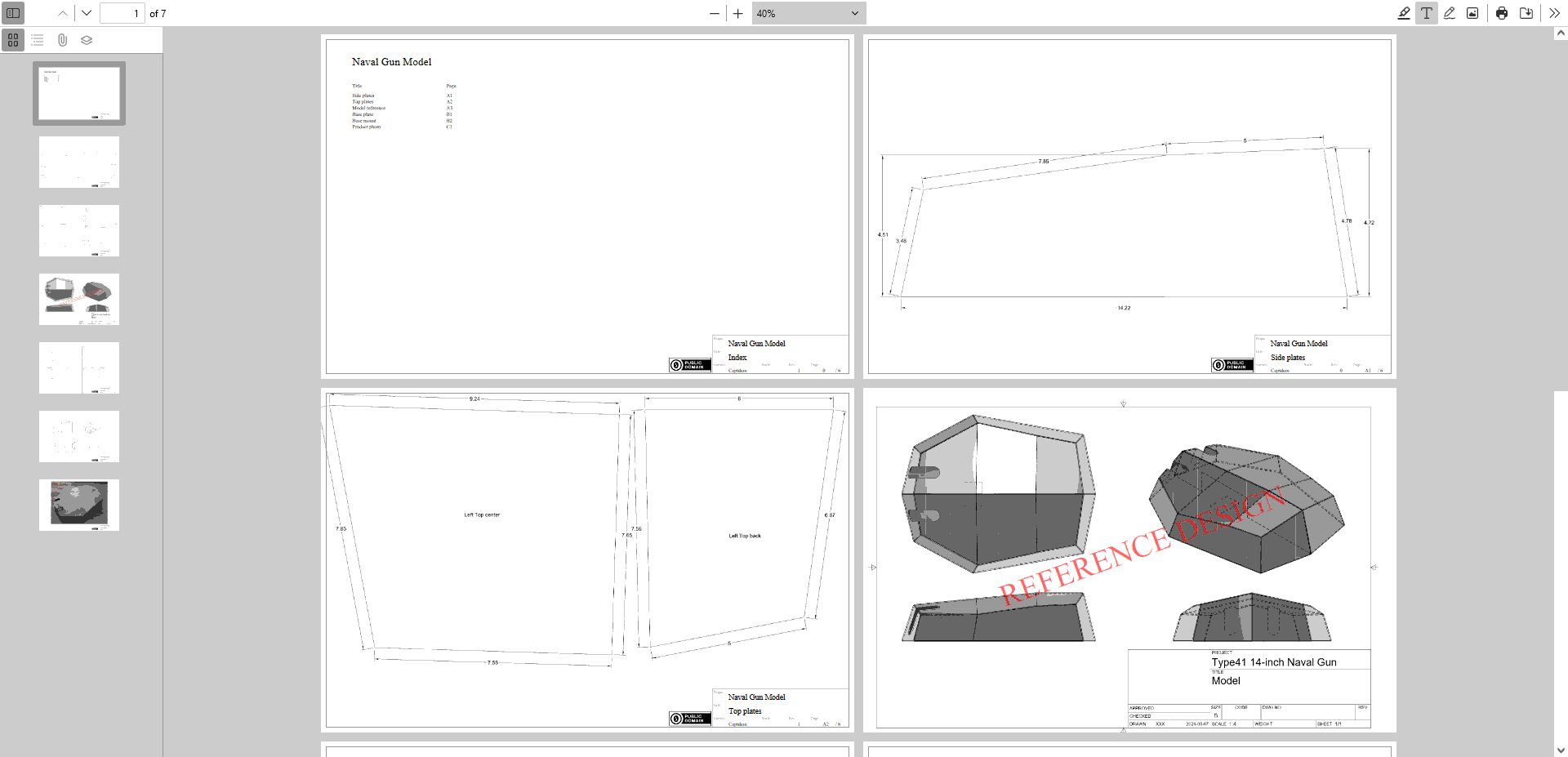
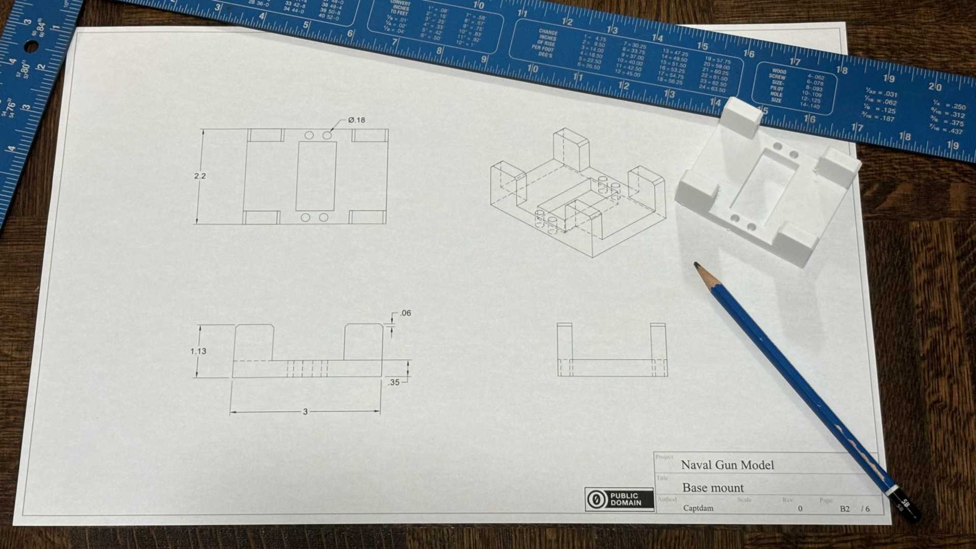
Following example contains a drawing package of an index page, two PDF drawings, a scan reference document in PNG and a product photo in JPEG. To simplify this demo, we will use a minified titleblock instead of standard titleblock.
Source files



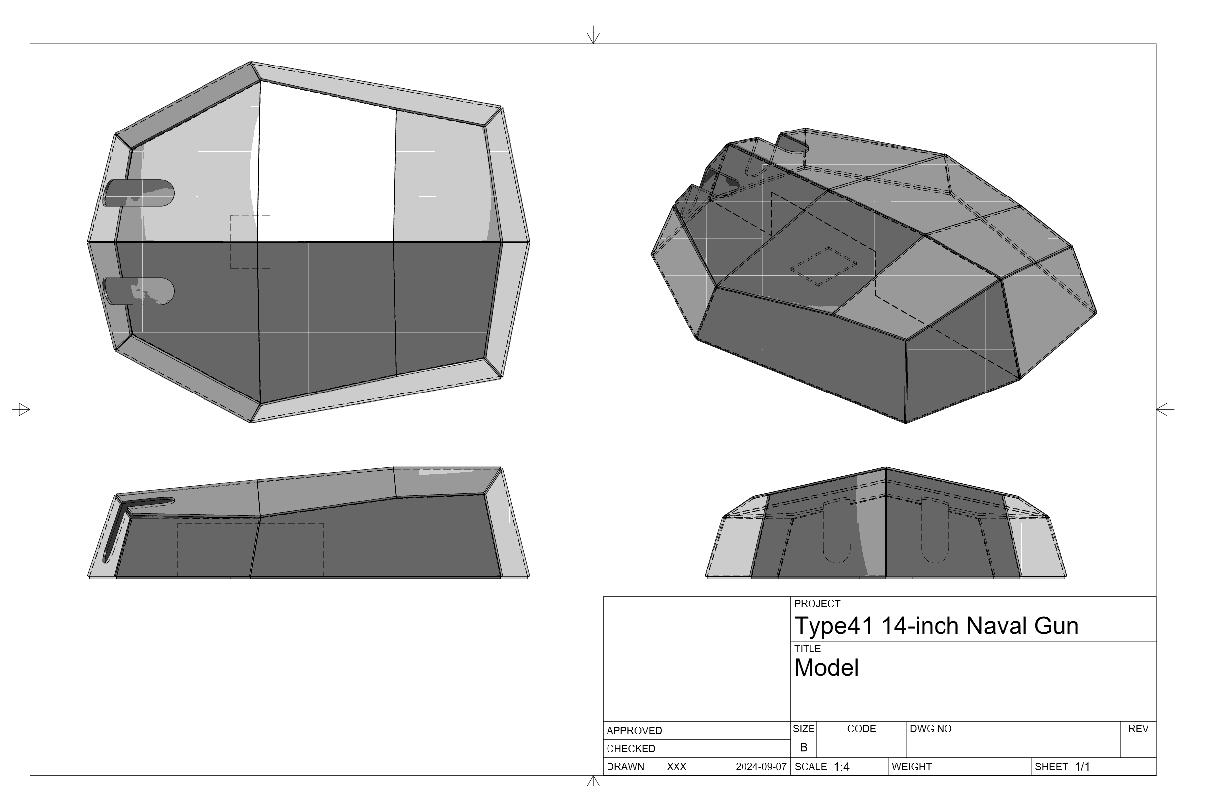

The index
We would like to make the first page to be the index page of the drawing package with titleblock. There is what we do:
Create a blank 17x11-inch page.
@BLANK,17,11Insert titleblock as a PNG image the same size as the page with transparent background at origin (0,0). Therefore, the titleblock image will cover the entire page.
P,0,0,17,11,0,tb.pngPlace project name, page title, page number, total page count, author name and reversion number on the page at the specific locations.
T,13,1.05,0.25,0.3,0,0,0,1,0,Naval Gun Model	// Project name
T,13,0.6,0.25,0.3,0,0,0,1,0,Index		// Page title
T,16,0.23,0.16,0.2,0,0,0,1,0,0			// Page number
T,16.4,0.23,0.16,0.2,0,0,0,1,0,/ 6		// Page count
T,13,0.23,0.16,0.2,0,0,0,1,0,Captdam		// Author
T,15.2,0.23,0.16,0.2,0,0,0,1,0,1		// Reversion
Place the project name at top of the page using a large font size. Place index title.
T,1,10,0.35,0.4,0,0,0,1,0,Naval Gun Model
T,1,9.3,0.16,0.2,0,0,0,1,0,Title
T,4,9.3,0.16,0.2,0,0,0,1,0,Page
Lookup fields in this index file and place them onto the page. In this example, we have two fields to be indexed. The first field is the 33th column of the index file, which is the page title; the second field is the 44th column of the index file, which is the page number. We will start the index from the 2nd row (we don’t need to include the index page in our index), and we will index 6 rows.
I,1,9,0.16,0.2,0,0,0,1,0,33,2,6
I,4,9,0.16,0.2,0,0,0,1,0,44,2,6
For the second and third page, we would like to include two pages from our first PDF file “1.pdf”. Furthermore, for the 5th and 6th page, we would like to include two pages from another PDF file “2.pdf”. So, we do:
Include a PDF file and specify the page number and rotation. In the example, we select the 1st page from “1.pdf”, no rotation.
1.pdf,1,0Insert title block and place all the necessary text fields, same as step 2 to 4 of the index page.
P,0,0,17,11,0,tb.png				// Titleblack
T,13,1.05,0.25,0.3,0,0,0,1,0,Naval Gun Model	// Project name
T,13,0.6,0.25,0.3,0,0,0,1,0,Side plates		// Page title
T,16,0.23,0.16,0.2,0,0,0,1,0,A1			// Page number
T,16.4,0.23,0.16,0.2,0,0,0,1,0,/ 6		// Page count
T,13,0.23,0.16,0.2,0,0,0,1,0,Captdam		// Author
T,15.2,0.23,0.16,0.2,0,0,0,1,0,0		// Reversion
For the 4th page, we would like to include a scan of reference drawing “r1.png”. Since this drawing has its own titleblock, we shouldn’t draw our own titleblock on top of it. So, we do:
Create a blank 17x11-inch page.
@BLANK,17,11Although we don’t draw the titleblock and insert all the necessary text fields, we need these text fields to generate the index. We use the “X” notation to indicate dummy fields. In this way, these text fields won’t be inserted into the page but will still be read by the indexer.
X,Naval Gun Model	// Project name
X,Model reference	// Page title
X,A3			// Page number
X,/ 6			// Page count
X,Joe Doe		// Author
X,As-is			// Reversion
Insert the picture “r1.png” the same size as the page at origin (0,0), so, the scanned reference document will cover the entire page.
P,0,0,17,11,0,r1.pngPlace a semi-transparent red text with some degrees of rotation on the page to indicate “Reference Design”.
T,4.5,4,1,1.5,1,0,0,0.5,20,REFERENCE DESIGN
For the last page, we would like to have a photo of the product. We also want titleblock for this page. We can do:
Create a blank 17x11-inch page.
@BLANK,17,11Insert title block and place all the necessary text fields, same as step 2 to 4 of the index page.
P,0,0,17,11,0,tb.png				// Titleblack
T,13,1.05,0.25,0.3,0,0,0,1,0,Naval Gun Model	// Project name
T,13,0.6,0.25,0.3,0,0,0,1,0,Product photo	// Page title
T,16,0.23,0.16,0.2,0,0,0,1,0,C1			// Page number
T,16.4,0.23,0.16,0.2,0,0,0,1,0,/ 6		// Page count
T,13,0.23,0.16,0.2,0,0,0,1,0,Captdam		// Author
T,15.2,0.23,0.16,0.2,0,0,0,1,0,0		// Reversion
Insert the photo “photo.jpg” at an appropriate place and size.
P,2.5,1.5,12,9,0,photo.jpg
