AVR Function stack
This article will discuss demonstrate the stack operation of AVR-GCC when calling a function from the hardware's perspective of view.
AVR, GCC, Stack, Function frame, SP, Stack pointer, FP, Frame pointer
--by Captdam @ Mar 3, 2025Index
Stack Overview
In case you are not familiar with computer hardware architecture, the CPU sees memory as a stack. Stack is a First-In-Last-Out memory. a.k.a. FILO.
The CPU also has a pointer named stack pointer, or SP. Stack pointer is always pointed to the top of the stack. It tells the CPU where to read and write for certain operations.
Stacks can be grown upwards, so the SP increases as more data writes to the stack; stack can also be grown downwards. AVR’s stack grows downwards.
SP can be pointed to the next available-to-write address, meaning that data will be written to the indicated address, then the stack moves; SP can also be pointed to last-wrote address, meaning that stack will move to next position, then the write to stack occurs. AVR’s SP is pointed to the next available-to-write address.
Push will write a piece of data on the top of the stack and move the SP to the next address. A second push will write data on top of the first push.
Pop (or pull) will read a piece of data from the top of the stack and move the SP back. A second pop will read the data under the first pop.
CPUs generally have 3 memory addressing modes:
- Direct addressing has the memory address encoded in instruction, used when the address is known at compile time.
- Indirect addressing (pointer addressing) uses the value inside a register (some architectures support an offset encoded in instruction), used when the address needs to be computed at run-time.
- The third is stack pointer addressing (I cannot find the right name for it, so I make this name), which is similar to indirect addressing, but with a special pointer, the SP. Some architectures give SP special functionalities, for example, push / pop can write / read memory and automatically increase / decrease the SP. Other architectures (for example, MIPS) don't have a SP, but use generally purpose register to simulate the SP.
Following is a mini program demonstrates the operation of push and pop instructions. You can turn off the auto run and manually reset / index the program to study the operation.
Note: This machine uses 2 bytes of memory space to store 16-bit long PC (Program Counter).
Function Overview
Return Address
CPU executes instructions (binary code) in the program memory. At the beginning of a function, the CPU changes the execution location from caller’s instruction to calleee’s instruction. At the end of the function, the CPU changes the execution location back to the caller from callee.
At the architecture level, the CPU uses a PC (Program counter) to track the location of execution. After finishing an instruction, the PC increases by 1 (in fact, by the length of the just-executed instruction), so it points to the next instruction.
When the CPU reads a “call function at address XXX” instruction (for AVR, call XXX), where the XXX represents the memory address of the callee function, the CPU will:
- Push the current PC’s content into the stack, where the PC’s content is the address of the next instruction of the caller.
- Modify the PC to that address. This eventually changes the execution location from the caller to the callee.
When the CPU reads a “return” instruction (for AVR, ret), the CPU will pop the content of the stack, and write it to the PC. Recall that, at the beginning of the function call, the CPU pushes the address of the next instruction of the caller into the stack. That means, the PC is now modified to the address of the next instruction of the caller. This eventually changes the execution location from the callee to the caller.
Following is a mini program demonstrates the operation of calling a callee function from caller function; then return back to the caller.
Note the address of next instruction (0x8003 for f1, 0x8005 for f2 in this example) will be pushed into stack.
Special Case - Modify Return Address
As you may have noticed, the CPU relays on the stack to track the return address of the function. If the content in the stack is mistakenly modified, the CPU loses track of the return address. If the stack pointer itself is mistakenly modified, the CPU will read data in another address and use it as a return address. In either case, the program won’t function correctly, and may cause a segment fault due to CPU executes instruction at invalid address.
As far as I know, no high-level language allows programmers to operate stack (I mean the real stack, not the stack memory structure you create from a data array), nor allowing operation on the SP, including C language; except using inline assembly or memory map to the stack.
However, in some cases, we may want to modify the return address stored in the stack. Imaging a multi-tasking program, function A may call a suspend function to suspend function A and start function B. In this suspend function, function A’s registers will be saved into memory or disk, then the registers will be replaced by function B’s data. At the end, function B’s instruction address is loaded into the stack. When returning from this suspend function, the CPU will go to function B’s address.
Following is a mini program demonstrates the operation of context switch between function A and function B.
Function A's and B's variables are saved in memory as static variables during context switch.
Callee Stack
Frame
Local variables (Variables declared inside function) are stored in a segment of stack memory named frame. Frame is generally above the return address. Shown below:
Frame Pointer
Recall that, CPUs are able to address data in memory using direct addressing or indirect addressing. For indirect addressing, the CPU uses a pointer (base address) and an offset to address a piece of data. This mode is used when the address of the data is unknown at compile time, and needs to be calculated at run time.
Since function calls can happen at any time, by any caller, and a function can be called by the function itself, we are not able to determine the address of a function's variables at compile time. However, before allocating space for local variables at the beginning of function, we can use the SP to determine the starting location of these variables. We will make a copy of the SP before we push all local variables into the stack. This copy is our stack pointer.
A pointer is used to indicate the start of the frame (in other words: the base address of the frame, the address of the first local variable), named frame pointer. This pointer can be used to address data (local variables) in the frame.
Following general assembly code program shows how to access local variable 2:
	mov IX, SP             ; Copy current SP into index register X (Note: not AVR assembly)
	push v0, v1, v2, v3    ; Push local variables into stack (frame), SP is now at N-4 due to the push instructions, but IX is still at N+0
	mov ACC, IX[-2]        ; Read data pointed by IX with offset -2, which is (N+0) - 2 = N-2
AVR Indirect Addressing Mode
The above concept may looks good, but AVR does not work in this way.
If the stack grows upwards, local variables will have higher address than the initial SP (that is when entering the function). In this case, indirect addressing supporting positive offset will work. If the stack grows downwards, local variables will have lower address than the initial SP. In this case, indirect addressing supporting negative offset will work. Sadly, AVR's stack grows downwords but its indirect addressing only supports positive offset.
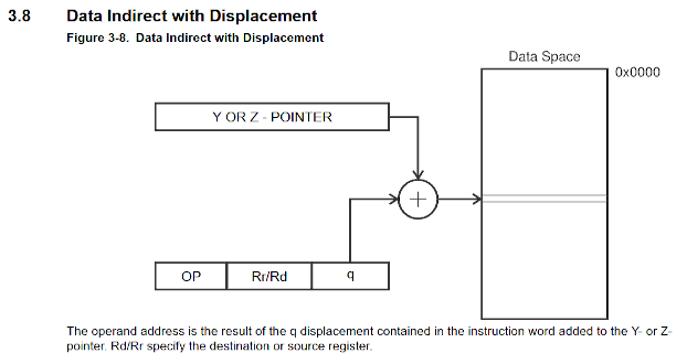
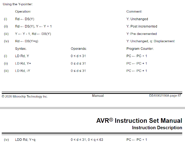
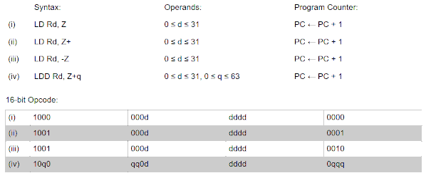
As the AVR instruction set manual shows, AVR allows load a data from memory pointed by register Y (R29:R28) or Z (R31:R30) plus an offset of 0 to 63 to a general purpose rigister. That means, the AVR indirect addressing mode will not be able to address any data below the Y or Z register.
AVR-GCC Frame Pointer
Let’s start by creating a simple function: creating a variable stackdata. Since this variable is a local variable, it should be saved in the stack.
#include <stdint.h>

void function() {
	volatile uint8_t stackdata = 0xAB;
}
Compilers tend to use registers instead of memory to store variables because registers are fast, and the CPU can only perform operations on registers (for AVR). Compiler only saves variables in memory when it runs out of registers. We use volatile keywords to prevent the compiler optimizing so we can observe the stack operation.
avr-gcc -O3 1.c -o 1.out
avr-objdump -m avr2 -d 1.out > 1.asm
Compile, then disassemble.
1.out:     file format elf32-avr

Disassembly of section .text:

00000000 <function>:
   0:	cf 93       	push	r28
   2:	df 93       	push	r29
   4:	1f 92       	push	r1
   6:	cd b7       	in	r28, 0x3d	; 61
   8:	de b7       	in	r29, 0x3e	; 62
   a:	8b ea       	ldi	r24, 0xAB	; 171
   c:	89 83       	std	Y+1, r24	; 0x01
   e:	0f 90       	pop	r0
  10:	df 91       	pop	r29
  12:	cf 91       	pop	r28
  14:	08 95       	ret
AVR-GCC uses register Y (R29:R28) as the frame pointer. As the AVR-GCC ABI stated: R28 and R29 are callee-saved registers, meaning the caller won’t expect any change on these registers after the callee function returns; therefore, R28 and R29 must be saved before we write anything (clobber) it.
Both register Y (R29:R28) and register Z (R31:R30) support indirect addressing with offset, register Y is callee-saved register but register Z is caller-saved register. Therefore, using register Z will not require the callee function to explicitly backup them, which can save a few cycles and program memory. But the AVR-GCC developers decided to use register Y. I guess they want to reserve register Z for memory program read purposes because only register Z can be used with LPM (Load program memory) instruction.
To store register Y, push r28 and push r29 instructions are issued at the very beginning of the callee function. To restore register Y, the pop r29 and pop r28 instructions are issued at the very end of the function, just before the ret instruction.
To allocate the space for the variable stackdata, AVR-GCC uses push r1 instruction, this will store the content of r1 into the stack and move the SP down for 1 slot. The content in R1 does not matter, all we need here is to move the SP down for 1 slot which essentially allocates 1 byte of space in the stack.
At the moment, we have finished allocating the callee frame. We can copy the content of SP (at address 0x3E:0x3D) to our frame pointer register Y, using the in r28, 0x3d and in r29, 0x3e instructions.
Recall that, AVR stack grows downwards, and the AVR SP always points to the next available-to-write location, the frame pointer is now pointed to the location just below the last variable in the stack.
To address the variable stackvariable, we will use indirect addressing instruction std y+1, r24: Write to memory address pointed by register Y with an offset of 1.
Below shows how AVR-GCC enters a function and allocate the callee stack.
Restoring stack at End of Function
Let's go back to the previous example:
1.out:     file format elf32-avr

Disassembly of section .text:

00000000 <function>:
   0:	cf 93       	push	r28
   2:	df 93       	push	r29
   4:	1f 92       	push	r1
   6:	cd b7       	in	r28, 0x3d	; 61
   8:	de b7       	in	r29, 0x3e	; 62
   a:	8b ea       	ldi	r24, 0xAB	; 171
   c:	89 83       	std	Y+1, r24	; 0x01
   e:	0f 90       	pop	r0
  10:	df 91       	pop	r29
  12:	cf 91       	pop	r28
  14:	08 95       	ret
The call instruction works by pushing the PC into stack (which contains the return address) and then changing the PC to callee’s instruction address. The ret (return) instruction works by popping the return address out from the stack and then writing it to the PC. The key is, the call instruction pushes the return address on the top of the stack; hence the ret instruction expects the return address to be on the top of the stack.
Therefore, it is important that the callee function must restore the stack: how much data it pushes into the stack, how much data it must pop out the stack. In other words, before executing the ret instruction, the SP must be the same as it after entering the function.
In the example above, pop r0 instruction is used to deallocate the local variable. Then, pop r29 and pop r28 instruction is used to restore the register Y.
The compiler must keep a track of the SP. If the SP at the moment executing the ret instruction differs from it after entering the function, the return instruction will load a wrong return address. This will cause the CPU to return to a invalid location in the program memory, causing unexpected behaviour and in PC world, the infamous possible segment fault.
Note: If the stack grows upwards or if the indirect addressing mode supports negative offset, the frame pointer can be the same as the initial SP since it can address the local data from that position. In this case, simply copying the FP to SP can restore the stack. Then, the compiler doesn’t need to keep track of the stack, allowing more flexible code.
// With negative offset addressing
FP = SP; // at data -1 (return address)
push(data0);
do_soemthing(FP[-1]); //data0
if (cond) {
	push(data1); // Less push
	do_soemthing(FP[-2]); //data1
} else {
	push(data1); // More push
	push(data2);
	do_soemthing(FP[-2]); //data1
	if (cond) {
		push(data3); // Even more push
		do_soemthing(FP[-4]); //data3
	}
}
SP = FP;
return;
// Without negative offset addressing
push(data0); // SP at return address + 1
FP = SP;
do_soemthing(FP[0]); //data0
if (cond) {
	push(data1); // Less push; SP at return address + 2
	FP = SP;
	do_soemthing(FP[0]); //data1
	pop(); // SP at return address + 1
} else {
	push(data1); // More push; SP at return address + 2
	push(data2); // SP at return address + 3
	FP = SP;
	do_soemthing(FP[1]); //data1
	if (cond) {
		push(data3); // Even more push; SP at return address + 4
		FP = SP;
		do_soemthing(FP[0]); //data3
		pop(); // SP at return address + 3
	}
	pop(); // SP at return address + 2
	pop(); // SP at return address + 1
}
pop(); // SP at return address + 0
return;
AVR-GCC stack allocatation
In the above example, AVR-GCC uses the push X instruction to allocate 1 byte of space to the local variable in the stack.
Following code shows how AVR-GCC allocates 2 bytes of space:
#include <stdint.h>

#define SIZE 2

void function() {
	volatile uint8_t stackdata[SIZE];
	stackdata[SIZE-1] = 0xFF;
}
00000000 <function>:
   0:	cf 93       	push	r28
   2:	df 93       	push	r29
   4:	00 d0       	rcall	.+0      	; 0x6 - Relative call: to the next line (so, no effect on PC)
   6:	cd b7       	in	r28, 0x3d	; 61
   8:	de b7       	in	r29, 0x3e	; 62
   a:	8f ef       	ldi	r24, 0xFF	; 255
   c:	8a 83       	std	Y+2, r24	; 0x02
   e:	0f 90       	pop	r0
  10:	0f 90       	pop	r0
  12:	df 91       	pop	r29
  14:	cf 91       	pop	r28
  16:	08 95       	ret
In this example, AVR-GCC doesn’t use two push instructions to allocate 2 bytes of space; instead, it uses a rcall .+0 (relative call) instruction.
If you write Python a lot, you may think the computer tracks the layer of function, as you make indentation in your source code. (In fact, some high-level language uses a software way to keep track of call stack.) This is not the case for AVR (and other architectures), the CPU doesn’t track the layer of function call. A call instruction simply pushes the return address into the stack, a ret simply pop return address from the stack. There is no register or any sort of mechanism to record the depth of function call.
AVR’s program memory is 16-bit long, meaning pushing the return address into the stack will consume 2 bytes of space of the stack and move the SP down for 2 slots. Instead of issuing two push instructions which will consume 2 program memory words, using rcall has the same effect but only consumes 1 program memory word.
What if we need more local variables? For example, 128 bytes of local variable, more than the max offset of indirect addressing mode (64 bytes). Following code shows how AVR-GCC allocates 128 bytes of space:
#include <stdint.h>

#define SIZE 128

void function() {
	volatile uint8_t stackdata[SIZE];
	stackdata[SIZE-1] = 0xFF;
}
00000000 <function>:
   0:	cf 93       	push	r28
   2:	df 93       	push	r29
   4:	cd b7       	in	r28, 0x3d	; 61
   6:	de b7       	in	r29, 0x3e	; 62
   8:	c0 58       	subi	r28, 0x80	; 128
   a:	d1 09       	sbc	r29, r1
   c:	0f b6       	in	r0, 0x3f	; 63
   e:	f8 94       	cli
  10:	de bf       	out	0x3e, r29	; 62
  12:	0f be       	out	0x3f, r0	; 63
  14:	cd bf       	out	0x3d, r28	; 61
  16:	8f ef       	ldi	r24, 0xFF	; 255
  18:	c0 58       	subi	r28, 0x80	; 128
  1a:	df 4f       	sbci	r29, 0xFF	; 255
  1c:	88 83       	st	Y, r24
  1e:	c0 58       	subi	r28, 0x80	; 128
  20:	d0 40       	sbci	r29, 0x00	; 0
  22:	c0 58       	subi	r28, 0x80	; 128
  24:	df 4f       	sbci	r29, 0xFF	; 255
  26:	0f b6       	in	r0, 0x3f	; 63
  28:	f8 94       	cli
  2a:	de bf       	out	0x3e, r29	; 62
  2c:	0f be       	out	0x3f, r0	; 63
  2e:	cd bf       	out	0x3d, r28	; 61
  30:	df 91       	pop	r29
  32:	cf 91       	pop	r28
  34:	08 95       	ret
Let's take a close look into the code:
   0:	cf 93       	push	r28
   2:	df 93       	push	r29
   4:	cd b7       	in	r28, 0x3d	; 61
   6:	de b7       	in	r29, 0x3e	; 62
Push register Y into stack to make a backup for it. Then, copy the SP into FP (using register Y).
   8:	c0 58       	subi	r28, 0x80	; 128
   a:	d1 09       	sbc	r29, r1

   c:	0f b6       	in	r0, 0x3f	; 63
   e:	f8 94       	cli
  10:	de bf       	out	0x3e, r29	; 62
  12:	0f be       	out	0x3f, r0	; 63
  14:	cd bf       	out	0x3d, r28	; 61
Using FP to calculate the SP after pushes all 128 bytes of local data into the stack. Since the local data will not be initialized (no actual value provided in the C code), we don't need to actually push them into the stack. Instead, we only need to move the SP down by 128 slots for 128 bytes of local data.
To do this, we will minus the FP (holds the SP value) by 128. AVR-GCC first uses subi r28, 0x80 (subtract with immediate value) to subtract the lower portion of the FP by 128 (note: FP and SP are 16-bit long). Because there is possibility of underflow when performing 8-bit operation on 16-bit data, AVR-GCC then uses sbc r29, r1 (subtract with carry) for the higher portion. As the AVR-GCC ABI stated, R1 always contains 0.
Although the FP can be used to address any data in the stack, we must write the calculated address in FP back to SP to actually allocate the space in the stack. So, when calling any child function or when an ISR is raised, the new stack position is in effect.
Because SP is 2 bytes long, and we will need 2 write operations to write it (sadly, AVR has no multibyte memory write instruction, except for some SFRs like timer registers), there is chance of ISR raised between writing the higher and lower portion of SP, we must temporarily disable the global interrupt flag (a bit in SREG, address 0x3F) with cli (CLear global Interrupt flag). Once the SP write is finished, we restore the global interrupt flag.
It is unknown at compile time the state of the global interrupt flag. AVR-GCC can not analyze our code and assume the state of the global interrupt flag. Therefore, it uses R0 to back up SREG before disable the global interrupt flag; and write R0 back to SREG to restore the global interrupt flag.
stackdata[SIZE-1] = 0xFF; // stackdata[127] = 0xFF

  16:	8f ef       	ldi	r24, 0xFF	; 255
  18:	c0 58       	subi	r28, 0x80	; 128
  1a:	df 4f       	sbci	r29, 0xFF	; 255
  1c:	88 83       	st	Y, r24
  1e:	c0 58       	subi	r28, 0x80	; 128
  20:	d0 40       	sbci	r29, 0x00	; 0
Next, we will write constant value 0xFF to the last element in the array stackdata[127].
AVR-GCC first loads the constant value into R24 by ldi r24, 0xFF.
Because the indirecting addressing mode only supports offset up to 64, and the offset we are using is far beyond this limit. Therefore, AVR-GCC will calculate the address of the data stackdata[127] and use indirect addressing mode without offset, that is st Y, r24.
To calculate the address of data, we will need to add the offset (128, or 0x80) to the FP. Note that, SP points to the next available-to-write location, which is 1 byte below the address of this array stackdata[]; so, stackdata[127] is at SP + 128, or SP + 0x80.
Since AVR’s data address bus is 16-bit long, we have to add 0x0080 to SP and take consideration of carry when doing 8-bit arithmetic operations, just like what we did when calculating the FP.
AVR instruction set doesn’t have adic (add with immediate value and carry) instruction to allow us adding a 16-bit immediate value. One way is to load the higher portion into a temperate register and use adc (add with carry) instruction. Another way is to use sbci (subtract with immediate value and carry) to subtract the negative of the 16-bit immediate value: +0x0080 = -0xFF80. Since the offset is known at compile time, the compiler can easily calculate the negative of the offset to be used with the sbci instruction: subi r28, 0x80 for lower portion, sbci r29, 0xFF for higher portion.
Once the data write finished, we will need to restore the FP; that is, minus the offset back: subi r28, 0x80, sbci r29, 0x00.
  22:	c0 58       	subi	r28, 0x80	; 128
  24:	df 4f       	sbci	r29, 0xFF	; 255
  26:	0f b6       	in	r0, 0x3f	; 63
  28:	f8 94       	cli
  2a:	de bf       	out	0x3e, r29	; 62
  2c:	0f be       	out	0x3f, r0	; 63
  2e:	cd bf       	out	0x3d, r28	; 61
Before we return from the function, we have to restore the stack. Definitely, issue 128 pop instruction is not a good choice; instead, we add the FP (same as SP after local data allocation) with the size of local data (128 bytes), then write it to SP. Note the multibyte write to SP needs to temporarily disable the global interrupt flag.
  30:	df 91       	pop	r29
  32:	cf 91       	pop	r28
  34:	08 95       	ret
Restore register Y, then return.
If the previous example, we found that the AVR-GCC needs to perform a few extra steps to disable and restore the global interrupt flag when modifying the SP.
AVR-GCC cannot assume the state of global interrupt flag, but we as developer knows what we are doing. If we know the interrupt is disabled, we can add an attribute __attribute__((OS_main)) when define the function:
#include <stdint.h>

#define SIZE 128

__attribute__((OS_main)) void function() {
	volatile uint8_t stackdata[SIZE];
	stackdata[SIZE-1] = 0xFF;
}
00000000 <function>:
   0:	cd b7       	in	r28, 0x3d	; 61
   2:	de b7       	in	r29, 0x3e	; 62
   4:	c0 58       	subi	r28, 0x80	; 128
   6:	d1 09       	sbc	r29, r1
   8:	de bf       	out	0x3e, r29	; 62
   a:	cd bf       	out	0x3d, r28	; 61
   c:	8f ef       	ldi	r24, 0xFF	; 255
   e:	c0 58       	subi	r28, 0x80	; 128
  10:	df 4f       	sbci	r29, 0xFF	; 255
  12:	88 83       	st	Y, r24
  14:	c0 58       	subi	r28, 0x80	; 128
  16:	d0 40       	sbci	r29, 0x00	; 0
  18:	c0 58       	subi	r28, 0x80	; 128
  1a:	df 4f       	sbci	r29, 0xFF	; 255
  1c:	0f b6       	in	r0, 0x3f	; 63
  1e:	f8 94       	cli
  20:	de bf       	out	0x3e, r29	; 62
  22:	0f be       	out	0x3f, r0	; 63
  24:	cd bf       	out	0x3d, r28	; 61
  26:	08 95       	ret
There is significant decrease in code size.
Caller Stack
In the previous section, we have studied the callee stack; now, let’s take a look into the caller stack.
Before call a function, the caller needs to find a way to pass the function parameters to the callee. AVR-GCC uses a set of registers to do this.
#include <stdint.h>

extern uint8_t function(uint8_t, uint8_t);

void main() {
	volatile uint8_t x = function(0x81, 0x80);
}

// Use extern to tell the compiler the interface of the function (param structure) but don't worry about the content of it
00000000 <main>:
   0:	cf 93       	push	r28
   2:	df 93       	push	r29
   4:	1f 92       	push	r1
   6:	cd b7       	in	r28, 0x3d	; 61
   8:	de b7       	in	r29, 0x3e	; 62
   a:	60 e8       	ldi	r22, 0x80	; 128
   c:	81 e8       	ldi	r24, 0x81	; 129
   e:	00 d0       	rcall	.+0      	; 0x10 <main+0x10> Actual address will be resolved at link-time
  10:	89 83       	std	Y+1, r24	; 0x01
  12:	0f 90       	pop	r0
  14:	df 91       	pop	r29
  16:	cf 91       	pop	r28
  18:	08 95       	ret
In the example above, we assign 0x80 to the last parameter, 0x81 to the second last parameter. The disassemble code shows AVR-GCC uses R24 for the first parameter; R22 for the second parameter.
Order of Assigning Parameters (Evaluation Order)
The order of parameter evaluation, and the order of parameter pushing (or copy to register) are not specified in C. It is up to the specified compiler (or even specified version of that compiler) to decide the orders.
AVR-GCC will evaluate and push (or copy to register) parameters from right to left. In other words, the last parameter (most right parameter) will be evaluated and pushed first, then the second-last, and so on.
uint8_t x = 0b00000001;

void p1() { x =<< 1; } // Shift left
void p2() { x += 1; } // Plus 1

void main() {
	function(
		p1(), // Evaluated first: 0b00000001 << 1 = 0b00000010
		p2()  // Evaluated second:  0b00000010 + 1 = 0b00000011
	);
	print(x);
}

Get 0b00000011 (WRONG)
uint8_t x = 0b00000001;

void p1() { x =<< 1; } // Shift left
void p2() { x += 1; } // Plus 1

void main() {
	function(
		p1(), // Evaluated second: 0b00000010 << 1 = 0b00000100
		p2()  // Evaluated first:  0b00000001 + 1 = 0b00000010
	);
	print(x);
}

Get 0b00000100 (Correct)
Order of Passing Parameters
According to the AVR-GCC ABI, AVR-GCC sees registers as register pairs. Registers are used from high to low, from R25 to R8.
The first parameter will be passed on R24 if it is 8-bit; or on R25:R24 if it is 16-bit; or R25:R22 if it is 32-bit; or R25:R18 if it is 64-bit.
Same rule applied for remaining parameters for remaining registers. If the first parameter is 32-bit long and occupied R25:22, the second parameter will be passed on R20 if it is 8-bit; or on R21:R20 if it is 16-bit; or R21:R18 if it is 32-bit; or R21:R14 if it is 64-bit.
If it runs out of registers, extra parameters will be pushed into the stack. Unlike the pass-by-register parameters where a gap is presented if a parameter is 8-bit; pass-by-stack parameter will not have any gap.
Following code shows parameters are passed by register pair: R25:R24 for the first 8-bit parameter, R23:R22 is used for the second 8-bit parameter; although the higher portion is not used.
extern uint8_t function(uint8_t, uint8_t);

void main() {
	volatile uint8_t x = function(0x81, 0x80);
}
   a:	60 e8       	ldi	r22, 0x80	; 128
   c:	81 e8       	ldi	r24, 0x81	; 129
   e:	00 d0       	rcall	.+0
Following code shows parameters are passed: R25:R18 for the first 64-bit parameter, R17:R10 is used for the second 64-bit parameter, R9:R8 is used for the third 16-bit parameter.
extern uint8_t function(uint64_t, uint64_t, uint16_t);

void main() {
	volatile uint8_t x = function(0x82, 0x81, 0x80);
}
  1e:	80 e8       	ldi	r24, 0x80	; 128
  20:	88 2e       	mov	r8, r24         ; Only upper registers (R16-R31) can be used to load constant
  22:	91 2c       	mov	r9, r1          ; r1 is always 0

  24:	91 e8       	ldi	r25, 0x81	; 129
  26:	a9 2e       	mov	r10, r25
  28:	b1 2c       	mov	r11, r1
  2a:	c1 2c       	mov	r12, r1
  2c:	d1 2c       	mov	r13, r1
  2e:	e1 2c       	mov	r14, r1
  30:	f1 2c       	mov	r15, r1
  32:	00 e0       	ldi	r16, 0x00	; 0
  34:	10 e0       	ldi	r17, 0x00	; 0

  36:	22 e8       	ldi	r18, 0x82	; 130
  38:	30 e0       	ldi	r19, 0x00	; 0
  3a:	40 e0       	ldi	r20, 0x00	; 0
  3c:	50 e0       	ldi	r21, 0x00	; 0
  3e:	60 e0       	ldi	r22, 0x00	; 0
  40:	70 e0       	ldi	r23, 0x00	; 0
  42:	80 e0       	ldi	r24, 0x00	; 0
  44:	90 e0       	ldi	r25, 0x00	; 0
  46:	00 d0       	rcall	.+0
Following code shows parameters are passed: R25:R18 for the first 64-bit parameter, R17:R10 is used for the second 64-bit parameter, stack is used for the third 64-bit parameter, stack is used for the forth 8-bit parameter, stack is used for the fifth 8-bit parameter.
extern uint8_t function(uint64_t, uint64_t, uint64_t, uint8_t, uint8_t);

void main() {
	volatile uint8_t x = function(0x83, 0x82, 0x81, 0x80, 0x40);
}
  1a:	80 e4       	ldi	r24, 0x40	; 64
  1c:	8f 93       	push	r24

  1e:	80 e8       	ldi	r24, 0x80	; 128
  20:	8f 93       	push	r24

  22:	1f 92       	push	r1
  24:	1f 92       	push	r1
  26:	1f 92       	push	r1
  28:	1f 92       	push	r1
  2a:	1f 92       	push	r1
  2c:	1f 92       	push	r1
  2e:	1f 92       	push	r1
  30:	81 e8       	ldi	r24, 0x81	; 129
  32:	8f 93       	push	r24

  34:	82 e8       	ldi	r24, 0x82	; 130
  36:	a8 2e       	mov	r10, r24
  38:	b1 2c       	mov	r11, r1
  3a:	c1 2c       	mov	r12, r1
  3c:	d1 2c       	mov	r13, r1
  3e:	e1 2c       	mov	r14, r1
  40:	f1 2c       	mov	r15, r1
  42:	00 e0       	ldi	r16, 0x00	; 0
  44:	10 e0       	ldi	r17, 0x00	; 0

  46:	23 e8       	ldi	r18, 0x83	; 131
  48:	30 e0       	ldi	r19, 0x00	; 0
  4a:	40 e0       	ldi	r20, 0x00	; 0
  4c:	50 e0       	ldi	r21, 0x00	; 0
  4e:	60 e0       	ldi	r22, 0x00	; 0
  50:	70 e0       	ldi	r23, 0x00	; 0
  52:	80 e0       	ldi	r24, 0x00	; 0
  54:	90 e0       	ldi	r25, 0x00	; 0
  56:	00 d0       	rcall	.+0
Note that:
- R9:R8 is not used: the third parameter is too large to be saved using available registers, so, they are pushed into the stack. Although the forth parameter is small enough to be fit into R8, it is more consistent to save it after the third parameter (in the stack).
- No gap in the stack between the two 8-bit parameters (in the stack).
- In the stack, higher portion of a parameter is pushed before the lower portion. Because AVR stack grows downwards, higher portion of the parameter (MSB) will have higher address in the memory.