ATtiny based WS2812 Light Bar Controller
This article shows how to use AVR MCU (ATtiny) to efficiently drive WS2812 LEDs, that is, using parallel signals to drive segmented LED stripe.
WS2812, LED, LED stripe, AVR, ATtiny, Assembly, Segment design, Parallel signal
--by Captdam @ Aug 18, 2025Index
Frame Format
LED Bit format
WS2812 uses PWM signals to send 0 and 1 bits. In each bit, the high signal first for a specific period, then the low signal. Depending on the length of the high portion, it can mean a 0-bit (short high level) or a 1-bit (long high level).
Raw Timing
Different manufacturers and models use different timing specifications. In most cases, the high level period is less than 0.5 microseconds for 0-bit; or larger than 0.5 microseconds for 1-bit. The low level period varies.
Following tables shows the timing diagram for some WS2812:
| Model | 0-bit High T0h | 0-bit Low T0l | 1-bit High T1h | 1-bit Low T1l | Bit Period | Reset |
|---|---|---|---|---|---|---|
| Timing diagram |
|
|
Tnh + Tnl | |||
| XL-6028RGBW-WS2812B | X-250-470 | X-1000-X | 580-850-1000 | X-400-X | 1200-1250-X | 80,000+ |
| XL-5050RGBW-WS2812B-HM | 200-295-350 | 550-595-1200 | 550-595-1200 | 200-295-350 | 900-X-X | 80,000+ |
| XL-3210RGBC-WS2812B | 300-X-X | 900-X-X | 900-X-X | 300-X-X | 1200-X-X | 200,000+ |
| Worldsemi WS2812 | 220-X-380 | 580-X-1000 | 580-X-1000 | 580-X-1000 | N/A | 280,000+ |
| Worldsemi WS2812C-2020-V1/W | 220-X-380 | 580-X-1000 | 580-X-1000 | 580-X-1000 | N/A | 280,000+ |
| Worldsemi WS2812B | 250-400-550 | 700-850-1000 | 650-800-950 | 300-450-600 | 650-1250-1850 | 50,000+ |
As we can see, it is chaotic. Different manufacturers, different models, completely different timing. It is hard to find a universal timing that fits all. Furthermore, when buying WS2812 LEDs on eBay or Amazon, the vendor only states WS2812, and there is no way to tell which manufacturer and which specific model it is. Unless buying a whole reel (so you can see the label), the best solution is to test it to find the actual timing; and of course, do not mix them (unless after testing the timing compatibility).
Timing for CPU clocked @ 8MHz
Although you are allowed to use any frequency between 0 to 20MHz to clock the AVR, a low-cost system will use the internal 8MHz RC clock (in that way, we can save a crystal, two capacitors, and get two free IOs to use). That means, every CPU cycle is 125 nanoseconds. Therefore, in terms of CPU cycles, to send a 1 or 0:
RC clock frequency is voltage and temperature dependen! Calibrate RC clock is required to ensure timing correctness. Note the ambient temperature change will cause clock frequency change; hence making the output signal longer or shorter than the required timing length. Ensure there is some safe margin. (Example: 3 cycles is 375 nanoseconds, that too close to 380)
RC clock frequency can be calibrated slightly off the 8MHz standard frequency to satisfy LED timing requirement.
| Model | 0-bit High T0h | 0-bit Low T0l | 1-bit High T1h | 1-bit Low T1l | Bit Period | Reset |
|---|---|---|---|---|---|---|
| XL-6028RGBW-WS2812B | X-2-3 | X-8-X | 5-7-8 | X-3-X | 10-10-X | 640+ |
| XL-5050RGBW-WS2812B-HM | 2-2-2 | 5-5-9 | 5-5-9 | 2-2-2 | 8-X-X | 640+ |
| XL-3210RGBC-WS2812B | 3-X-X | 8-X-X | 8-X-X | 3-X-X | 10-X-X | 1600+ |
| Worldsemi WS2812 | 2-X-3 | 5-X-8 | 5-X-8 | 5-X-8 | N/A | 2240+ |
| Worldsemi WS2812C-2020-V1/W | 2-X-3 | 5-X-8 | 5-X-8 | 5-X-8 | N/A | 2240+ |
| Worldsemi WS2812B | 2-3-4 | 6-7-8 | 6-6-7 | 2-3-4 | 6-10-14 | 400+ |
Timing for CPU clocked @ 16MHz
If you want to clock the CPU at 16MHz (like Arduino) using external crystal:
Some AVRs come with internal PLL to achieve higher clock frequency without the need of external crystal and clock input pins.
| Model | 0-bit High T0h | 0-bit Low T0l | 1-bit High T1h | 1-bit Low T1l | Bit Period | Reset |
|---|---|---|---|---|---|---|
| XL-6028RGBW-WS2812B | X-4-7 | X-16-X | 10-14-16 | X-6-X | 20-20-X | 1280+ |
| XL-5050RGBW-WS2812B-HM | 4-5-5 | 9-10-19 | 9-10-19 | 4-5-5 | 15-X-X | 1280+ |
| XL-3210RGBC-WS2812B | 5-X-X | 15-X-X | 15-X-X | 5-X-X | 20-X-X | 3200+ |
| Worldsemi WS2812 | 4-X-6 | 10-X-16 | 10-X-16 | 10-X-16 | N/A | 4480+ |
| WorldsemiWS2812C-2020-V1/W | 4-X-6 | 10-X-16 | 10-X-16 | 10-X-16 | N/A | 4480+ |
| Worldsemi WS2812B | 4-6-8 | 12-14-16 | 11-13-15 | 5-7-9 | 11-20-29 | 800+ |
Timing for CPU clocked @ 20MHz
If you want to clock the CPU at max frequency (20MHz) using external crystal:
| Model | 0-bit High T0h | 0-bit Low T0l | 1-bit High T1h | 1-bit Low T1l | Bit Period | Reset |
|---|---|---|---|---|---|---|
| XL-6028RGBW-WS2812B | X-5-9 | X-20-X | 12-17-20 | X-8-X | 24-25-X | 1600+ |
| XL-5050RGBW-WS2812B-HM | 4-6-7 | 11-12-24 | 11-12-24 | 4-6-7 | 18-X-X | 1600+ |
| XL-3210RGBC-WS2812B | 6-X-X | 18-X-X | 18-X-X | 6-X-X | 24-X-X | 4000+ |
| Worldsemi WS2812 | 5-X-7 | 12-X-20 | 12-X-20 | 12-X-20 | N/A | 5600+ |
| Worldsemi WS2812C-2020-V1/W | 5-X-7 | 12-X-20 | 12-X-20 | 12-X-20 | N/A | 5600+ |
| Worldsemi WS2812B | 5-8-11 | 14-17-20 | 13-16-19 | 6-9-12 | 13-25-37 | 1000+ |
Example: XL-5050RGBW-WS2812B-HM & Worldsemi WS2812B with CPUs at Different Clocks
Let's use XL-5050RGBW-WS2812B-HM and Worldsemi WS2812B with CPUs at different clocks as out next example:
| Model | 0-bit High T0h | 0-bit Low T0l | 1-bit High T1h | 1-bit Low T1l | Bit Period |
|---|---|---|---|---|---|
| Timing diagram |
|
|
Tnh + Tnl | ||
| XL-5050RGBW-WS2812B-HM | |||||
| Raw timing | 200-295-350 | 550-595-1200 | 550-595-1200 | 200-295-350 | 900-X-X |
| CPU cycles @ 8MHz | 2 cycles / 250 ns | 6 cycles / 750 ns | 6 cycles / 750 ns | 2 cycles / 250 ns | 8 cycles / 1000 ns |
| CPU cycles @ 16MHz | 5 cycles / 312.5 ns | 10 cycles / 625 ns | 10 cycles / 625 ns | 5 cycles / 312.5 ns | 15 cycles / 937.5 ns |
| Worldsemi WS2812B | |||||
| Raw timing | 250-400-550 | 700-850-1000 | 650-800-950 | 300-450-600 | 650-1250-1800 |
| CPU cycles @ 8MHz | 3 cycles / 375 ns | 7 cycles / 875 ns | 6 cycles / 750 ns | 4 cycles / 500 ns | 10 cycles / 1250 ns |
| CPU cycles @ 16MHz | 6 cycles / 375 ns | 14 cycles / 875 ns | 13 cycles / 812.5 ns | 7 cycles / 437.5 ns | 20 cycles / 1250 ns |
8MHz is too slow for XL-5050RGBW-WS2812B-HM. See reason in next section.
Furthermore, both 0-bit and 1-bit starts with a high level. At a specific cycle (2nd cycle for this example), we will send the data (high for 1-bit, low for 0-bit). At another specific cycle (6th cycle for this example), we send low.
It is clear to say, the timing requirement is tight for our application when the CPU is running at 8MHz. We will have to buffer the data in SRAM, and then burst output the data to satisfy the timing requirement.
Reset
To reset (start a new stream), we will need to pull the signal low for a long period. Above examples shows 80 or 280 microseconds, but other models may varies.
This time period allows us to load the prepared data in SRAM for burst output.
Furthermore, we can utilize this time period to send data streams to other LEDs. For example, we can use 100 microseconds to send data to LED series A, use the next 100 microseconds to send data to LED series B. Once B is finished, we can go back to A, which is now ready for the next data stream.
LED Word format
Word mans a data unit. Its width depends on the application, it does NOT always mean 16-bit or 32-bit.
WS2812 supports 24-bit RGB color. That is, it takes 24 bits of data to program one LED. Green first, then red, then blue. MSB first.
Multiple LEDs are connected in series. We send a data stream to program them. The first LED in the series will consume the first 24 bits of data (bit 0 to bit 23); the second LED will consume the second 24 bits of data (bit 24 to bit 47), and so on.
8-Lane Parallel Bus
The more LEDs, the longer to take to program the entire light bar.
Furthermore, we are now using only 1 output bit. AVR (and other 8-bit MCUs) group 8-bit into a byte as a port. Bit output on ports is very inefficient.
To speed up the transmission, we can break the light bar into 8 segments. Next, we can use a 8-bit IO port to drive the segmented light bar, one bit for one segment.
As the above figure shows, the first byte output by the MCU will contain the first bit of all 8 segments, the second byte output by the MCU will contain the second bit of all 8 segments, and so on...
Example: 24 LEDs in 8 Segments
Following example shows 24 LEDs divided into 8 segments. That is, each segment has 3 LEDs.
With out segmented design, the controller should output:
		LED 0 G		LED 0 R		LED 0 B		LED 1 G		LED 1 R		LED 1 B		LED 2 G		LED 2 R		LED 2 B
Segment 0	0000 0000	0000 0001	0000 0010	0000 0100	0000 0101	0000 0110	0000 1000	0000 1001	0000 1010
Segment 1	0001 0000	0001 0001	0001 0010	0001 0100	0001 0101	0001 0110	0001 1000	0001 1001	0001 1010
Segment 2	0010 0000	0010 0001	0010 0010	0010 0100	0010 0101	0010 0110	0010 1000	0010 1001	0010 1010
Segment 3	0011 0000	0011 0001	0011 0010	0011 0100	0011 0101	0011 0110	0011 1000	0011 1001	0011 1010
Segment 4	0100 0000	0100 0001	0100 0010	0100 0100	0100 0101	0100 0110	0100 1000	0100 1001	0100 1010
Segment 5	0101 0000	0101 0001	0101 0010	0101 0100	0101 0101	0101 0110	0101 1000	0101 1001	0101 1010
Segment 6	0110 0000	0110 0001	0110 0010	0110 0100	0110 0101	0110 0110	0110 1000	0110 1001	0110 1010
Segment 7	0111 0000	0111 0001	0111 0010	0111 0100	0111 0101	0111 0110	0111 1000	0111 1001	0111 1010
With the segmented design, the controller should output:
Addr		X0/X8		X1/X9		X2/XA		X3/XB		X4/XC		X5/XD		X6/XE		X7/XF
0X		0000 0000	0000 1111	0011 0011	0101 0101	0000 0000	0000 0000	0000 0000	0000 0000
0X		0000 0000	0000 1111	0011 0011	0101 0101	0000 0000	0000 0000	0000 0000	1111 1111
1X		0000 0000	0000 1111	0011 0011	0101 0101	0000 0000	0000 0000	1111 1111	0000 0000
1X		0000 0000	0000 1111	0011 0011	0101 0101	0000 0000	1111 1111	0000 0000	0000 0000
2X		0000 0000	0000 1111	0011 0011	0101 0101	0000 0000	1111 1111	0000 0000	1111 1111
2X		0000 0000	0000 1111	0011 0011	0101 0101	0000 0000	1111 1111	1111 1111	0000 0000
3X		0000 0000	0000 1111	0011 0011	0101 0101	1111 1111	0000 0000	0000 0000	0000 0000
3X		0000 0000	0000 1111	0011 0011	0101 0101	1111 1111	0000 0000	0000 0000	1111 1111
4X		0000 0000	0000 1111	0011 0011	0101 0101	1111 1111	0000 0000	1111 1111	0000 0000
The first bit in each segment is 00000000; therefore, we output 00000000 in the beginning. The second bit in each segment is 00001111; therefore, we output 00001111 then. The third bit in each segment is 00110011; therefore, we output 00110011 next.
Look the pre-segmented data vertically; look the segmented data horizontally.
Driver Software
Bit Driver
As we discussed in the previous section, timing requirement is tight. Especially, for XL-5050RGBW-WS2812B-HM, the shorter signal only last 350 microseconds, that's even less than 3 cycles for 8MHz (375 microseconds). Therefore, the most important aspect of this driver is to be fast and accurate.
For each data bit, we will need to:
- At the beginning, set output high.
- Read the color data bit, and index the read pointer.
- At the some cycle, output the color data bit.
- At the some cycle, set output low.
- Check for the boundary of data stream (number of data bits in each segment).
- If it is not the last data bit, go to step 1.
- If it is the last data bit: Stop sending, keep the output low for a period. We can prepare data for the next output burst during this time.
Let’s write this task in C, assume we will be using PORTA on ATtiny461 to drive the LEDs:
1.c
#define SIZE (24 * 8) // 24 bits/LED

#include <avr/io.h>

volatile uint8_t data[SIZE];

void main() {
	DDRA = 0xFF;
	for (volatile uint8_t* p = data; p < &(data[SIZE]); p++) {
		PORTA = 0xFF;
		PORTA = *p;
		/* asm("nop\n"); */
		PORTA = 0x00;
	}
	for(;;);
}
Compile with avr-gcc 1.c -o 1.out -mmcu=attiny461 -O3.
The Evil for Loop with 16-bit Memory Addressing
Let's disassemble the above C code with avr-objdump -m avr25 -D 1.out > 1.txt:
00000048 <main>:
  48:	8f ef       	ldi	r24, 0xFF	; 255
  4a:	8a bb       	out	0x1a, r24	; 26
  4c:	e0 e6       	ldi	r30, 0x60	; 96
  4e:	f0 e0       	ldi	r31, 0x00	; 0
  50:	9f ef       	ldi	r25, 0xFF	; 255
  52:	9b bb       	out	0x1b, r25	; 27 === Cycle 0   ===
  54:	81 91       	ld	r24, Z+		; load needs 2 cycles
  56:	8b bb       	out	0x1b, r24	; 27 === Cycle 3   ===
  ...               	nop			;    === Cycle 3+n ===
  58:	1b ba       	out	0x1b, r1	; 27 === Cycle 4+n ===
  5a:	81 e0       	ldi	r24, 0x01	; 1
  5c:	e0 32       	cpi	r30, 0x20	; 32
  5e:	f8 07       	cpc	r31, r24
  60:	a8 f3       	brcs	.-16     	; 0x52 <main+0xa> === Cycle 8+n, plus another 2 cycles to jump to beginning of the loop ===
  62:	ff cf       	rjmp	.-2      	; 0x68 <main+0x20>
Problem:
- It takes at least 3 cycles to be able to send the data bit after pull the signal high. This makes driving XL-5050RGBW-WS2812B-HM with 8MHz clock impossible, but Worldsemi WS2812B is OK.
- It takes 5 cycles between pulling the signal low for current bit and pulling the signal high for next bit. The
forloop requires us to check for the boundaryp < &(data[SIZE]). Because the address is 16-bit long, AVR needs multiple cycles to perform the compute.
But... What if we can rearrange the instructions to perform the index check while the CPU is idling for timing (the nop instructions)?
Be Fast!
We have to use Assembly for this purpose:
2.c

#define SIZE (24 * 8) // 24 bits/LED

#include <avr/io.h>
uint8_t data[SIZE];

__attribute__((naked)) void burst(uint8_t* start, uint8_t* end) {
	asm(
		"movw	r30, r24\n\t"		// First argument in r25:r24, r31:r30 (Z) are call-used regs
		"ldi	r24, 0xFF\n\t"		// R24 is call-used, content in R24 copied to R30 and no loinger required
		// Loop starts
		"1:	\n\t"
		"out	%[port], r24\n\t"	// Cycle 0
		"ld	r25, Z+\n\t"		// R25 is call-used (load requires 2 cycles)
		"out	%[port], r25\n\t"	// Cycle 3
		"cp	r30, r22\n\t"		// Second argument in r23:r22
		"cpc	r31, r23\n\t"
		"out	%[port], r1\n\t"	// Cycle 6, R1 is always 0, OUT instruction will NOT clob zero flag
		"nop	\n\t"
		"nop	\n\t"
		"brne	1b\n\t"			// Cycle 9 and 10 (branch requires 2 cycles)
		"ret	\n\t"
		:
		: [port] "I" (_SFR_IO_ADDR(PORTA))
	);
}

void main() {
	DDRA = 0xFF;
	burst(data, &(data[SIZE]));
	for(;;);
}
Compile with avr-gcc 2.c -o 2.out -mmcu=attiny461 -O3.
Disassemble with avr-objdump -m avr25 -D 2.out > 2.txt:
00000048 <burst>:
  48:	fc 01       	movw	r30, r24
  4a:	8f ef       	ldi	r24, 0xFF	; 255
  4c:	8b bb       	out	0x1b, r24	; 27
  4e:	91 91       	ld	r25, Z+
  50:	9b bb       	out	0x1b, r25	; 27
  52:	e6 17       	cp	r30, r22
  54:	f7 07       	cpc	r31, r23
  56:	00 00       	nop
  58:	00 00       	nop
  5a:	1b ba       	out	0x1b, r1	; 27
  5c:	c1 f3       	brne	.-18     	; 0x4c <burst+0x4>
  5e:	08 95       	ret

00000060 <main>:
  60:	8f ef       	ldi	r24, 0xFF	; 255
  62:	8a bb       	out	0x1a, r24	; 26
  64:	60 e2       	ldi	r22, 0x20	; 32
  66:	71 e0       	ldi	r23, 0x01	; 1
  68:	80 e6       	ldi	r24, 0x60	; 96
  6a:	90 e0       	ldi	r25, 0x00	; 0
  6c:	ee df       	rcall	.-38     	; 0x48 <burst>
  6e:	ff cf       	rjmp	.-2      	; 0x6e <main+0xe>
We successfully satisfy the timing requirement.
This driver uses the AVR-GCC calling convention, it is compatible with AVR-GCC ABI ONLY!
Word Format Converter
Since we are using parallel design, we will have to convert the signal from the original GRB8.
Following C code shows how to perform the conversion:
#include <stdio.h>
#include <stdint.h>
#include <stdlib.h>
#include <errno.h>

typedef struct __attribute__((packed)) RGB {
	uint8_t r, g, b;
} RGB;
typedef struct __attribute__((packed)) Lane {
	uint8_t g[8];
	uint8_t r[8];
	uint8_t b[8];
} Lane;

int main(int argc, char* argv[]) {
	if (argc != 7) {
		fprintf(stderr, "Use: this leds segments lines frames source dest, (%d given)\n", argc);
		return 1;
	}
	int led = atoi(argv[1]);
	int segment = atoi(argv[2]);
	int line = atoi(argv[3]);
	int frame = atoi(argv[4]);
	fprintf(stderr, "%d LEDs per segment, %d segments, %d bits buffer, %d lines, %d frames\n", led, segment, led * segment * 24, line, frame);

	uint8_t* bin = malloc(led * segment * 3);
	uint8_t* bout = malloc(led * segment * 3);
	FILE* fin = fopen(argv[5], "rb");
	FILE* fout = fopen(argv[6], "wb");
	int pRead[segment]; // Offset in bit (not byte)
	int pWrite;

	for (int iframe = 0; iframe < frame; iframe++) {
		for (int iline = 0; iline < line; iline++) {
			pWrite = 0;
			for (int isegment = 0; isegment < segment; isegment++) {
				pRead[isegment] = isegment * led * 24; // Each segment has 24 * led bits
			}
			fread(bin, 3, led * segment, fin);
			for (int iled = 0; iled < led; iled++) {
				for (int ibit = 0; ibit < 24; ibit++) {
					for (int isegment = 0; isegment < segment; isegment++) {
						int readIdx = pRead[isegment] >> 3;
						int readBit = 7 - (pRead[isegment] & 0b111);
						uint8_t x = ( bin[readIdx] >> readBit ) & 1;
						pRead[isegment]++;
						//fprintf(stderr, "Read %d: Byte %d, bit %d: %d\n", ibit, readIdx, readBit, x);
						int writeIdx = pWrite >> 3;
						int writeBit = 7 - (pWrite & 0b111);
						uint8_t write = bout[writeIdx];
						write &= ~(1<<writeBit);
						write |= x << writeBit;
						bout[writeIdx] = write;
						pWrite++;
					}
				}
			}
			fwrite(bout, 3, led * segment, fout);
			for (int i = 0; i < 3 * led * segment; i++) {
				fprintf(stderr, "Write %d:\t", i);
				for (int j = 7; j >= 0; j--) {
					fprintf(stderr, "%c", '0' + ((bout[i] >> j) & 1));
				}
				fprintf(stderr, "\n");
				if (i % 8 == 0b111) fprintf(stderr, "\n");
			}
		}
	}

	free(bin);
	free(bout);
	fclose(fin);
	fclose(fout);
	return 0;
}
Compile with gcc -O3 image.c -o image
Assume we have 24 LEDs in 8 segments (so, 3 LEDs each segment). If we save the original GRB8 data in a file named test.in, and we are planning to generate the processed data in test.out, we can use the command: ./image 3 8 1 1 test.in test.out.
Following screenshot shows the example data before and after conversion:
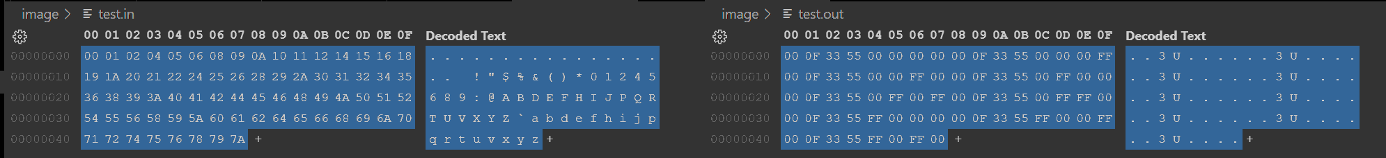
We should pre-process the data on a PC. Leting the MCU to process the data on-the-fly is way too heavy.
Hardware Selection
ATtiny Family MCU Selection
For maximum performance, we will need to use a MCU with at least one full 8-bit IO port.
According to my another blog, we have the following options:
- ATtint25 has only 5 IOs.
- ATtiny24 (or ATtiny441) has 12 IOs in 2 ports 8 in port A, 4 in port B. It will work, but, leaving limited pins for other functionality (communication is on port A).
- ATtiny261 is a nice choice. We can use port A for LED data output; port B for other purposes, such as receiving data using USI.
- ATtiny2313 is a nice choice. We can use port B for LED data output; port A and port D for other purposes, such as receiving data using USART.
Memory Size Selection
To satisfy the tight timing requirement, we will need to save the color data into SRAM buffer first, then burst output the data in the buffer.
Since each LED word is 24 bits and we are dividing the light bar into 8 segments, every 8 LEDs will need 24 bytes of buffer.
That means, theoretically, the maximum number of LEDs the ATtiny MCU could allow is:
| ATtiny model | SRAM size (Bytes) | Maxmium LED | Required buffer size | Free memory |
|---|---|---|---|---|
| 2X | 128 | 40 | 120 | 8 |
| 4X | 256 | 80 | 240 | 16 |
| 8X | 512 | 168 | 504 | 8 |
If you want larger buffer size, consider ATmega.
You may fabricate PCB and solder the LEDs on (if you really enjoy working with SMDs). However, probably the easiest way to make a WS2812-based light bar is to buy the commonly-used cost-effective light stripe, then stick it on a hard wood or metal plate.
These light stripes may have different densities, most common ones include 144 LEDs per meter, 60 LEDs per meter and 30 LEDs per meter. The following table helps you choose the right LED stripe according to your dimension requirement.
| Buffer | LEDs | 144/m | 60/m | 30/m |
|---|---|---|---|---|
| 120 | 40 | 0.278m | 0.667m | 1.333m |
| 240 | 80 | 0.556m | 1.333m | 2.667m |
| 504 | 160 | 1.167m | 2.8m | 5.6m |
| 1008 | 336 | 2.333m | 5.6m | 11.2m |
| 2040 | 680 | 4.722m | 11.333m | 22.667m |
Unit Test
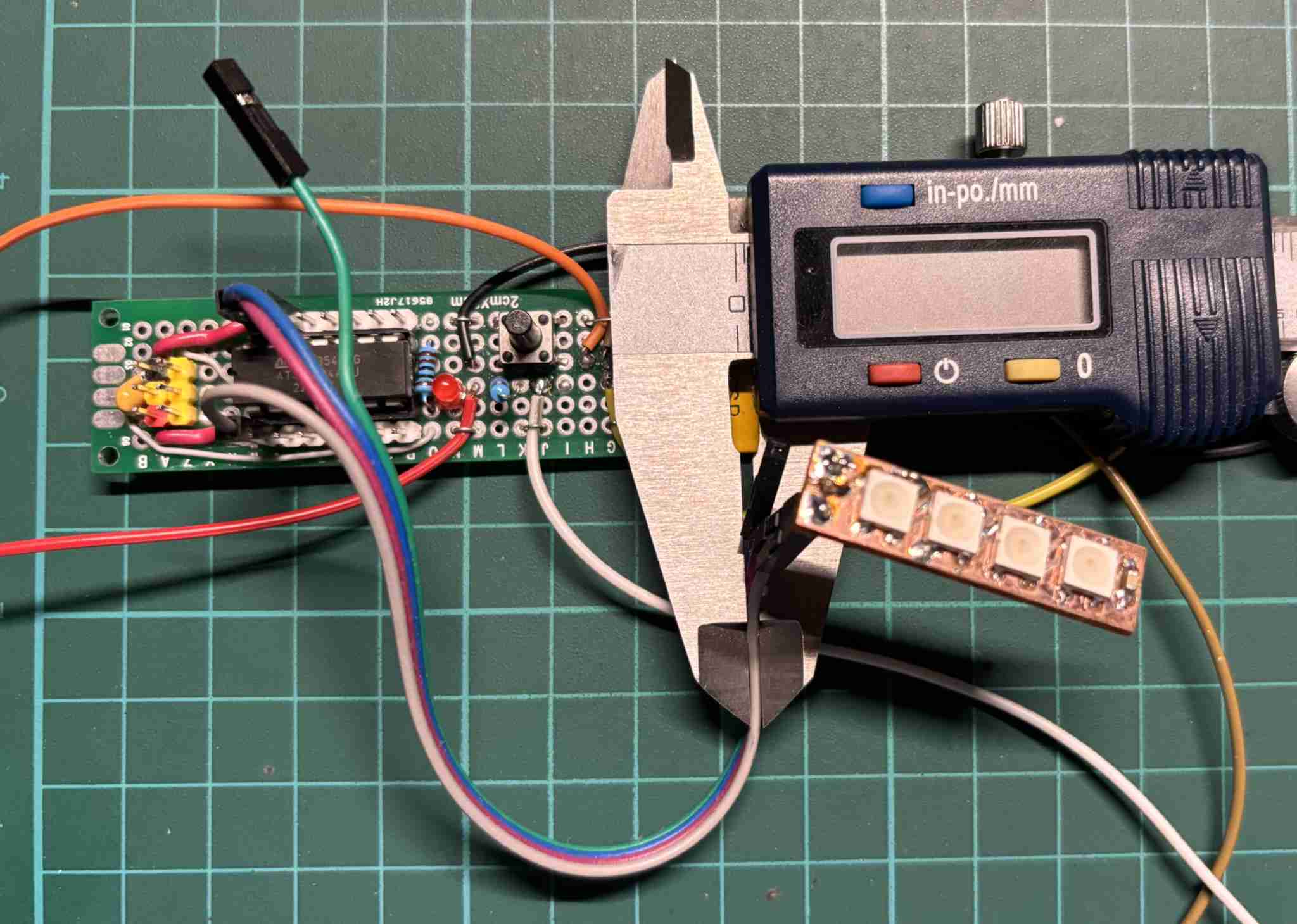
Test Circuit
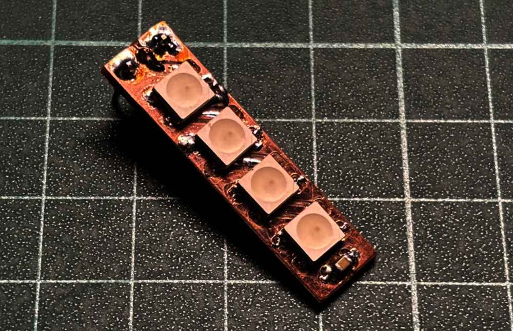
Now, we will build a 4-LED PCB test unit. This simulate a 1-segment 4-LED unit. Following diagram shows the PCB design, you can also cut a section of WS2812 stripe to build the test unit.
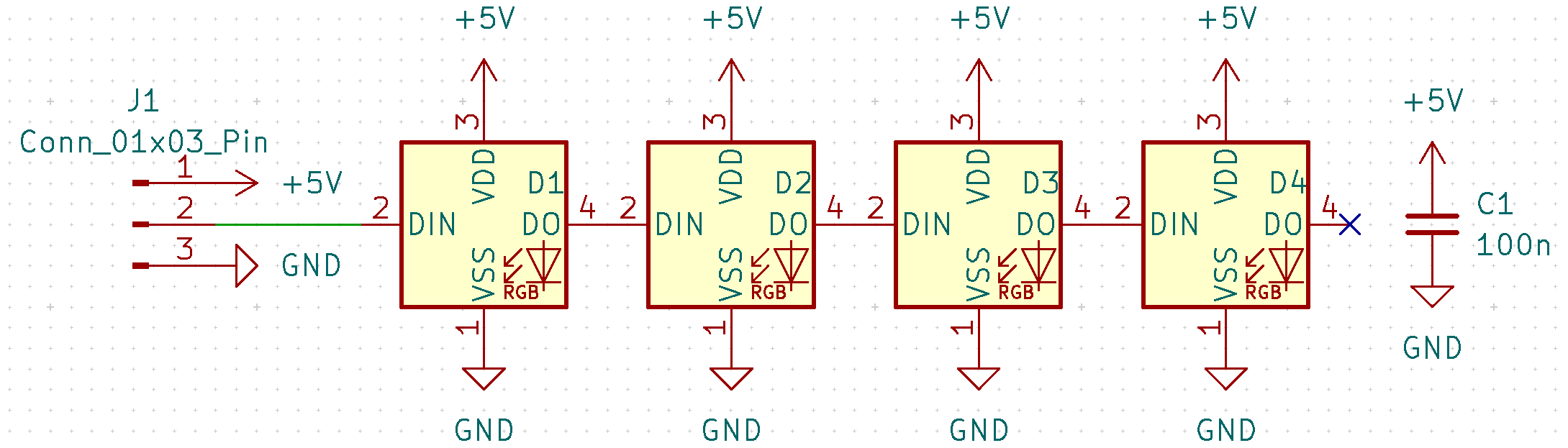
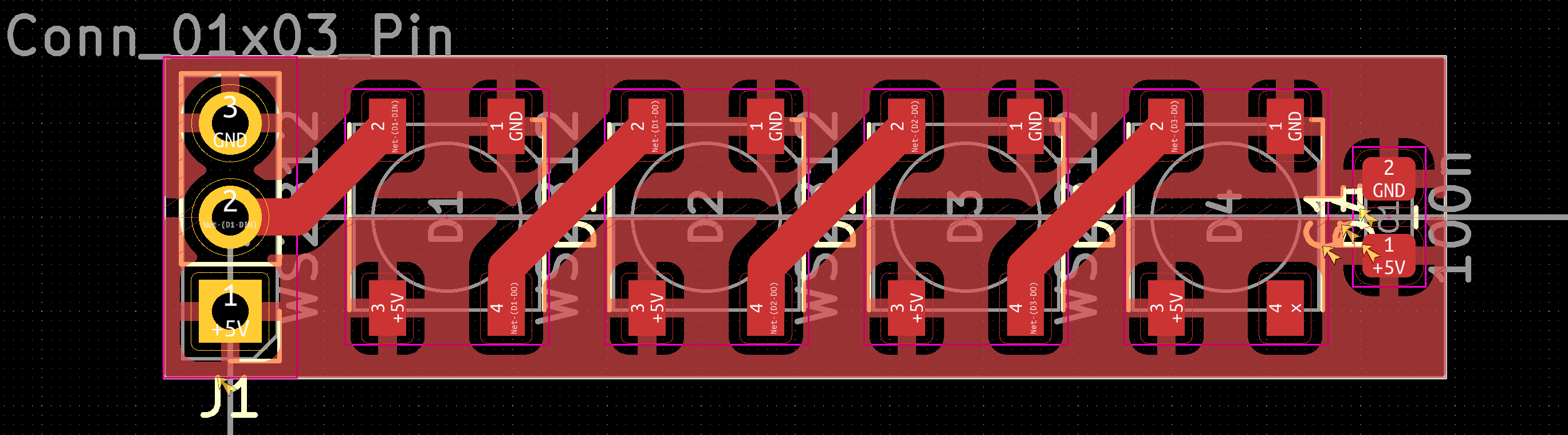
Here is the link to my KiCAD project for the test unit.
Note the signal input on left side, output on right side; however, the power is on bottom side, GND on top side. This is weird, I don't know why the guy designed the package to place power on lower side but GND on top.
We will connect the unit to a ATtiny44 MCU. The data input pin of the test unit will be connected to port A pin 0 of the MCU, which simulates segment 0.
All LEDs On with Different Color
#define SIZE (24 * 3) // 24 bits/LED, 8 segment, 3LEDs per segment

#include <avr/io.h>

uint8_t data[SIZE] = {
//	MSB 7 6     5     4     3     2     1     0 LSB

	/* LED 0 */
	0xFF, 0xFF, 0xFF, 0xFF, 0xFF, 0xFF, 0xFF, 0xFF, //Green
	0x00, 0x00, 0x00, 0x00, 0x00, 0x00, 0x00, 0x00, //Red
	0x00, 0x00, 0x00, 0x00, 0x00, 0x00, 0x00, 0x00, //Blue
	/* LED 1 */
	0x00, 0x00, 0x00, 0x00, 0x00, 0x00, 0x00, 0x00, //Green
	0xFF, 0x00, 0x00, 0x00, 0x00, 0x00, 0x00, 0x00, //Red
	0x00, 0x00, 0x00, 0x00, 0x00, 0x00, 0x00, 0x00, //Blue
	/* LED 2 */
	0x00, 0x00, 0x00, 0x00, 0x00, 0x00, 0x00, 0x00, //Green
	0x00, 0x00, 0x00, 0x00, 0x00, 0x00, 0x00, 0x00, //Red
	0x55, 0x00, 0x00, 0x00, 0x00, 0x00, 0x00, 0x00, //Blue

	/* Parallel design, each bit in a byte represents a segment */
};

__attribute__((naked)) void burst(uint8_t* start, uint8_t* end) {
	asm(
		"movw	r30, r24\n\t"		// First argument in r25:r24, r31:r30 (Z) are call-used regs
		"ldi	r24, 0xFF\n\t"		// R24 is call-used, content in R24 copied to R30 and no loinger required
		// Loop starts
		"1:	\n\t"
		"out	%[port], r24\n\t"	// Cycle 0
		"ld	r25, Z+\n\t"		// R25 is call-used
		"out	%[port], r25\n\t"	// Cycle 3
		"cp	r30, r22\n\t"		// Second argument in r23:r22
		"cpc	r31, r23\n\t"
		"out	%[port], r1\n\t"	// Cycle 6, R1 is always 0, OUT instruction will not clob zero flag
		"nop	\n\t"
		"brne	1b\n\t"			// Cycle 7 and 8
		"ret	\n\t"
		:
		: [port] "I" (_SFR_IO_ADDR(PORTA))
	);
}

int main() {
	DDRA = 0xFF;
	PORTA = 0x00;

	for (uint8_t d = 0; ; d++) {
		burst(data, &(data[SIZE]));

		for (uint32_t i = 0; i < 100000; i++); // Reset
	}

	return 0;
}
In the above example, we are driving 24 LEDs divided into 8 segments (So, 3 LEDs in each segment). We save the color data in array data[SIZE].
/* LED 0 */
0xFF, 0xFF, 0xFF, 0xFF, 0xFF, 0xFF, 0xFF, 0xFF, //Green
0x00, 0x00, 0x00, 0x00, 0x00, 0x00, 0x00, 0x00, //Red
0x00, 0x00, 0x00, 0x00, 0x00, 0x00, 0x00, 0x00, //Blue
The first 24 bytes contains the data for the first LED in each segment.
In this example, the MCU will write 11111111 00000000 00000000 to all segments. This will turn the green color at maximum intensity.
/* LED 1 */
0x00, 0x00, 0x00, 0x00, 0x00, 0x00, 0x00, 0x00, //Green
0xFF, 0x00, 0x00, 0x00, 0x00, 0x00, 0x00, 0x00, //Red
0x00, 0x00, 0x00, 0x00, 0x00, 0x00, 0x00, 0x00, //Blue
The second 24 bytes contains the data for the second LED in each segment.
In this example, the MCU will write 00000000 10000000 00000000 to all segments. This will turn the red color at half intensity.
/* LED 2 */
0x00, 0x00, 0x00, 0x00, 0x00, 0x00, 0x00, 0x00, //Green
0x00, 0x00, 0x00, 0x00, 0x00, 0x00, 0x00, 0x00, //Red
0x55, 0x00, 0x00, 0x00, 0x00, 0x00, 0x00, 0x00, //Blue
The third 24 bytes contains the data for the third LED in each segment.
We will need to look this example bitwisely. Because the first byte in bule channel is 0x55 (0b01010101), the MCU will write 00000000 00000000 10000000 to segment 0, 2, 4, 6; 00000000 00000000 00000000 to segment 1, 3, 5, 7. This will turn the bule color at half intensity for even segments; off for odd segments.
Since the buffer is 72 bytes large, the MCU will output 72 bits on each segment. Each LED will consume 24 bits of data; therefore, any LED after the 3rd LED will receive no data.
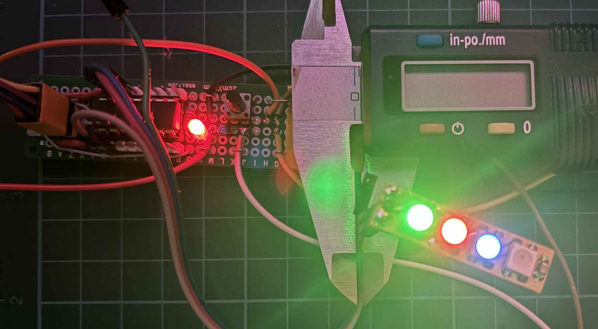
Program the MCU, we can see the first LED is green with maxmium intensity, the second and third LEDs are red and blue with half intensity.
The MCU is clocked at 8MHz, use avrdude -P com3 -c arduino -p t44 -U lfuse:w:0xa2:m to program the low fuse of ATtiny44 to use internal 8MHz RC clock.
Blinking LED
int main() {
	DDRA = 0xFF;
	PORTA = 0x00;

	for (uint8_t d = 0; ; d++) {
		data[0] = ~data[0];
		burst(data, &(data[SIZE]));
		for (uint32_t i = 0; i < 100000; i++); // Reset
		data[32] = ~data[32];
		burst(data, &(data[SIZE]));
		for (uint32_t i = 0; i < 100000; i++); // Reset
		data[64] = ~data[64];
		burst(data, &(data[SIZE]));
		for (uint32_t i = 0; i < 100000; i++); // Reset
	}

	return 0;
}
In this example, the MCU will toggle the MSB (first bit) of LED 0 green, LED 1 red and LED 2 blue, it will cause the LEDs in segment 0 light in the following patterns in loop:
| Time | LED 0 | LED 1 | LED 2 | Note |
|---|---|---|---|---|
| Init | 11111111-00000000-00000000 | 00000000-10000000-00000000 | 00000000-00000000-10000000 | Beginning pattern in buffer |
| 6n+1 | 01111111-00000000-00000000 | 00000000-10000000-00000000 | 00000000-00000000-10000000 | LED 0 gose half intensity |
| 6n+2 | 01111111-00000000-00000000 | 00000000-00000000-00000000 | 00000000-00000000-10000000 | LED 1 off |
| 6n+3 | 01111111-00000000-00000000 | 00000000-00000000-00000000 | 00000000-00000000-00000000 | LED 2 off |
| 6n+4 | 11111111-00000000-00000000 | 00000000-00000000-00000000 | 00000000-00000000-00000000 | LED 0 gose full intensity |
| 6n+5 | 11111111-00000000-00000000 | 00000000-10000000-00000000 | 00000000-00000000-00000000 | LED 1 half on |
| 6n+6 | 11111111-00000000-00000000 | 00000000-10000000-00000000 | 00000000-00000000-10000000 | LED 2 half on |
Now, program the MCU.
We can confirm the LEDs light on and off same as the pattern table above. Note the green intensity change.
Multi-Segment
In the next test, we will use a logic analyzer to read multiple lines at the same time.
First, we will assume our test data is saved in EEPROM; therefore, we will need to load it from EEPROM into SRAM in the beginning:
int main() {
	DDRA = 0xFF;
	PORTA = 0x00;

	for (uint8_t i = 0; i < SIZE; i++) {
		data[i] = eeprom_read_byte(i);
	}

	for (uint8_t d = 0; ; d++) {
		burst(data, &(data[SIZE]));
		for (uint32_t i = 0; i < 100000; i++); // Reset
	}

	return 0;
}
We will need to burn the test data into EEPROM when programming the MCU:
avr-gcc 3.c -o 3.out -mmcu=attiny44 -O3
avrdude -p t44 -P COM3 -c arduino -U flash:w:3.out -U eeprom:w:image/test.out:r
Power up, connect the output to logic analyzer, we will get:
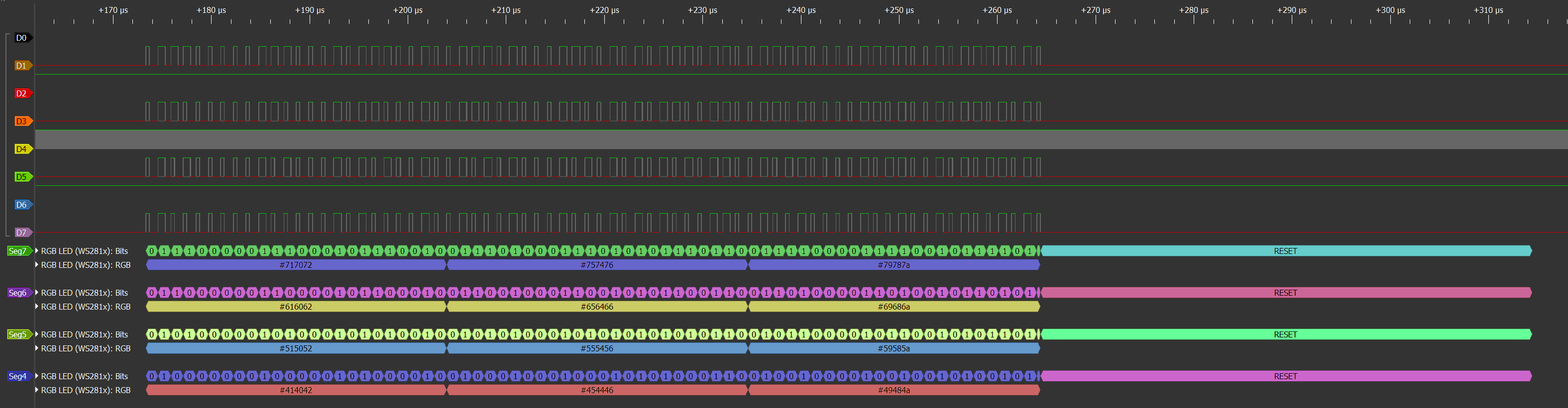
Recall that in previous section, the orginal data is shown in the left side, the converted data is shown in the right side:
We burned the data in right side into the EEPROM (converted data); the logic analyzer received the data same as the left side (orginal data).