MSC-51 Powered Nixie Clock
You can’t say no to nixie tubes if you are an electrical geek or you are a fan of Steins Gate, and you will want to build a clock using nixie tubes.
MSC-51, 89C52, Micro controller, MCU, Nixie tube, Clock
--by Captdam @ Feb 14, 2018- Also on GitHub: https://github.com/captdam/Nixie-tube-driver
- Here is the English version of this article
- 这里是这篇文章的中文版
Index
Hardware Design
Control Circuit
To control the clock, I used a microcontroller 89C52RC.This is a CISC MCU based on the legendary Intel MSC-51 architecture (aka 8051). It comes with 4 IO ports, that is 32 IOs. That’s why I selected this MCU, because it provides a lot of IOs with relatively low unit cost. Plus, I had too much surplus in my inventory I needed to get rid of.
Each nixie tube has 10 inputs (plus a common anode / cathode), representing the number 0 to 9. At any given moment, there will only be one active number. Which means, we will need to use log2(10) = 3.3 bits to operate 10 possibilities. Each port of the MCU has 8 bits; therefore, we can use each port to drive two digits. We can use a port for seconds, a port for minutes and a port for hours. We can use the left port as input for setting the clock.
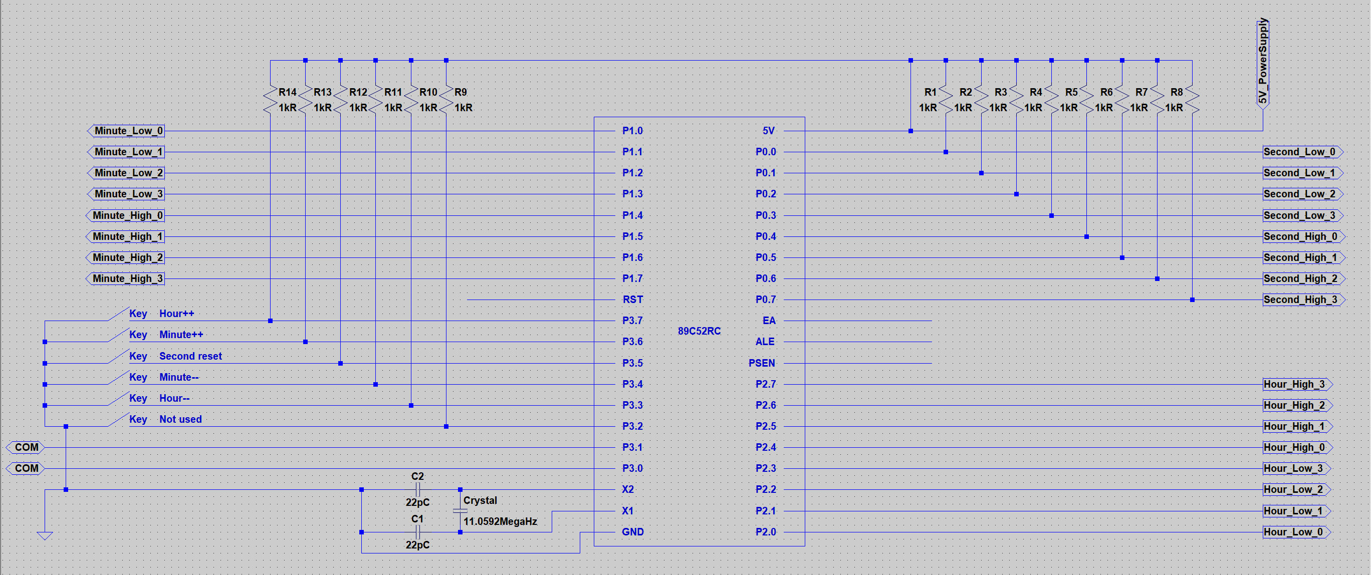
As the figure shows, we will use P0, P1 and P2 for seconds, minutes and hours, respectively. The lower 4 bits of a port will be used for 1s, and the higher 4 bits of a port will be used for 10s. For example, to display 15:22:08:
- Hour is 15. 1 for 10s, that is
0001in binary on higher nibble; 5 for 1s, that is0101in binary on lower nibble. So, P2 should output00010101in binary. - Minute is 22. 2 for 10s, that is
0010in binary on higher nibble; 2 for 1s, that is0010in binary on lower nibble. So, P1 should output00100010in binary. - Second is 08. 0 for 10s, that is
0000in binary on higher nibble; 8 for 1s, that is1000in binary on lower nibble. So, P0 should output00001000in binary.
Bit 3 to 7 in P3 are used for hour decrement, minute decrement, second reset, minute increment and hour increment, respectively.
Furthermore, we need to add pull up resistors R1 - R8 on P0 because 8051 doesn’t have an internal pullup on P0. We also need to add pull up resistorsR9 - R14 on inputs on P3 for weak pull up.
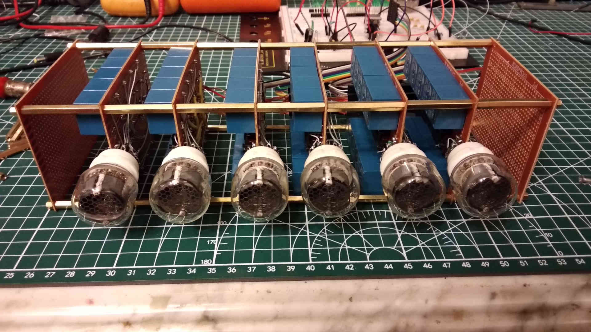
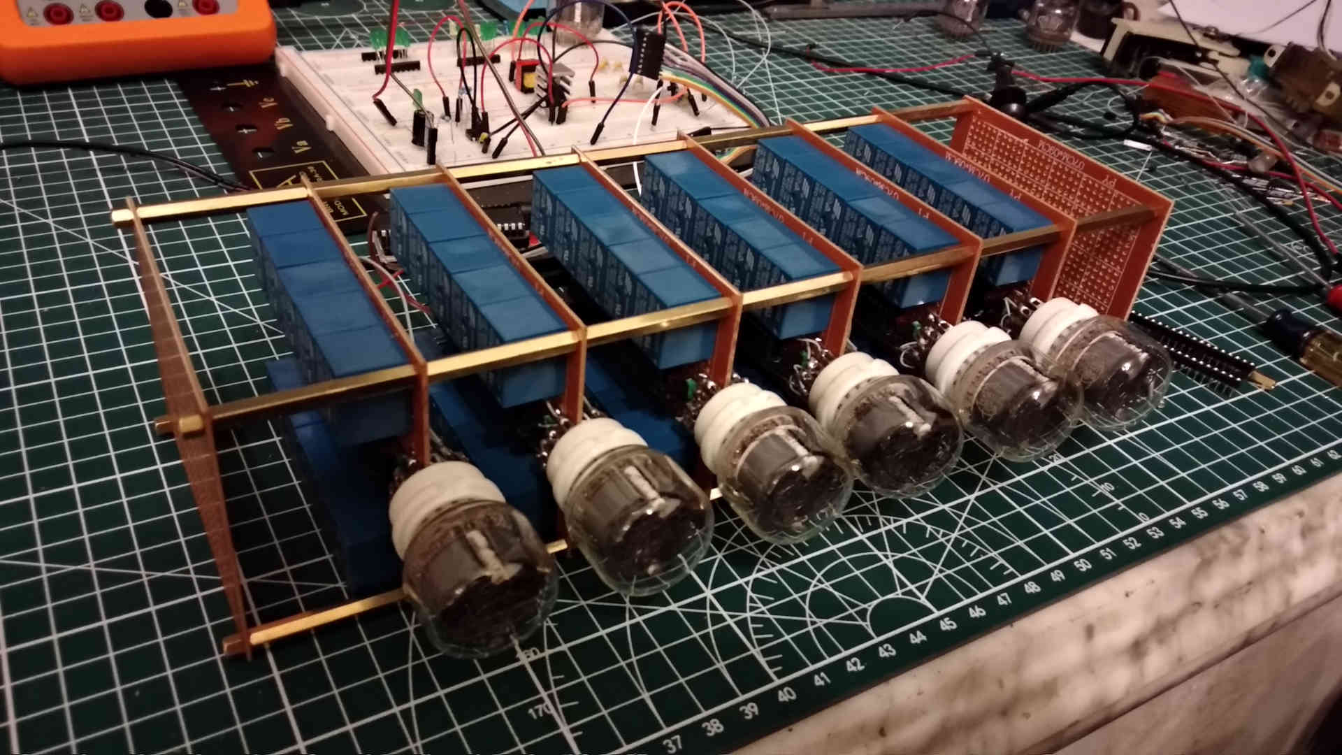
Driver Circuit
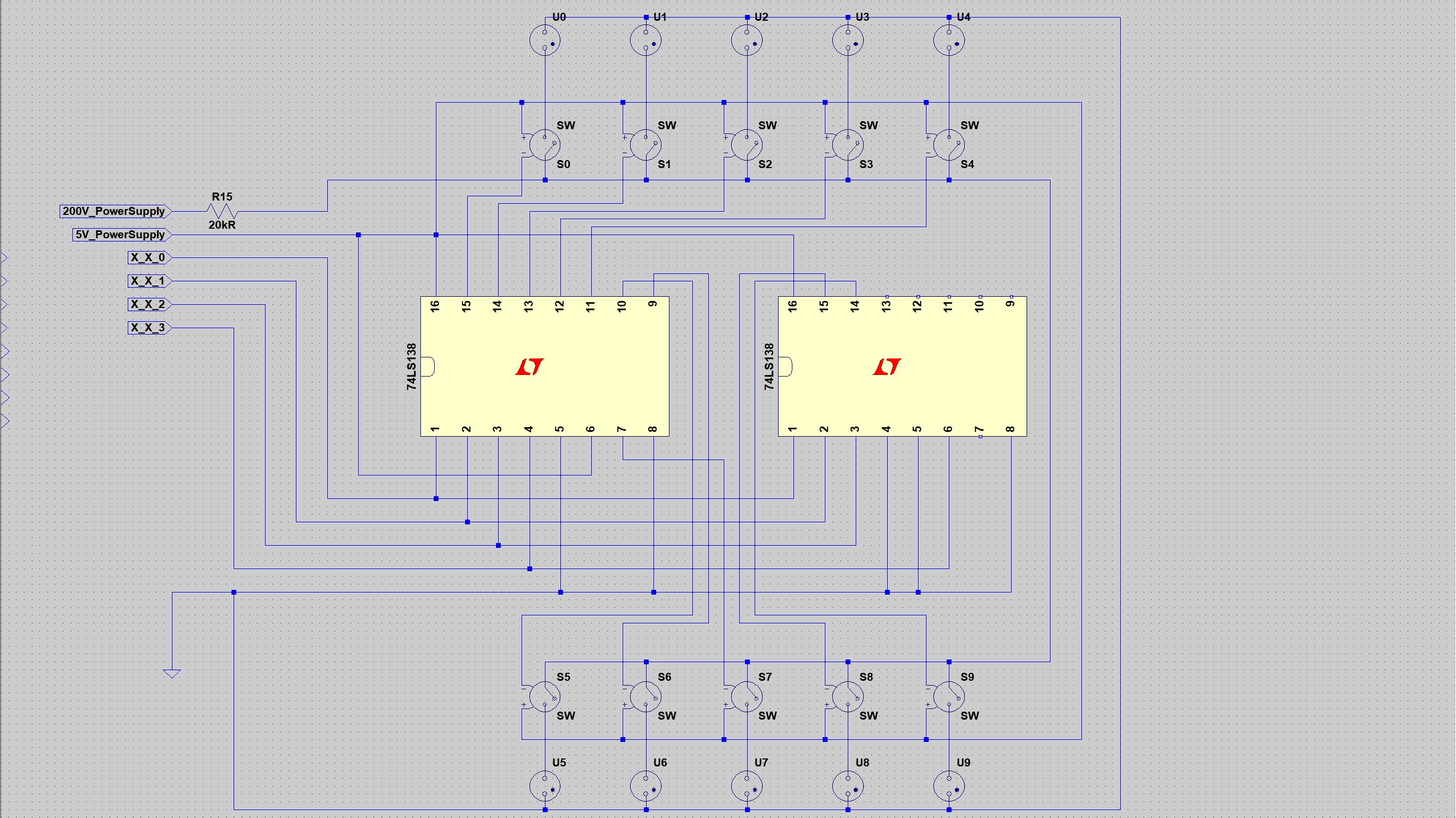
The binary signal provided by MCU must be converted to one-cold signal to be able to drive each number inside the nixie tube. We can use the 74LS138 decoder for this task. Furthermore, nixie tubes require high voltage as high as 150V or above to drive, that is far beyond the output voltage of MCU and (common) MOSFET. We will use relays to drive high voltage and provide some degree of physical isolation to protect our low voltage control circuit. Depending on the model of the nixie tube and the power voltage, we will need to add protection resistors in series with the nixie tubes for current limiting. I used 20k ohms resistors for my design.
We can also use One-hot signals with the 74LS238 decoder
The decoder provides sufficient current to drive the relay; therefore, we don’t need to add MOS to drive relays.
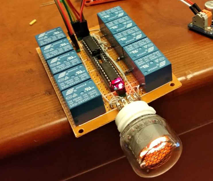
Above photo shows a driver circuit for one nixie tube. The 10 blue blocks on the sides of the PCB are relays; the black chips in the middle are the decodes. I placed chip sockets to allow me to swap chips if required.
Software Design
The software design is straightforward. We will create 3 8-bit integer variables for second, minute and hour. We will reset them and the associated output at power up.
Furthermore, we will need to create a timer interrupt that fires every second. In the interrupt, we will increase the by 1. If the second reaches 60, we reset it to 0 and increase the minute by 1. If the minute reaches 60, we reset it and increase the hour by 1. If the hour reaches 24, we reset it. It is grade 1 math, but in programming.
Other than that, we will need to check user inputs for setting time. We can do this byu adding an interrupt for each input button, but that will make the program design complex. It may also cause errors if the MCU is busy processing user input and cannot process the timer event immediately when required. Therefore, I decide to introduce polling of user input at the end of each timer interrupt.
The 8051 is 12T MCU, meaning it requires 12 crystal cycles to finish one operation. Because the crystal is 11.0529MHz,that means the number of operation perform by the MCU per second is:
1s * (11.0529MHz / 12) = 1s * 11.0529M op/s / 12 = 921075 ops
The 8051 MCU comes with a 16-bit timer, that is, the maximum number it can hold will be around 65k, this is far below the required 921k we just calculated. So, we will need to extend the timer resolution to 24-bit using a software approach.
921075 = 100 * 9210
The timer will fire an interrupt every 9210 cycles. After 100 interrupts (the software portion reaches 100), we will reset it and execute the second increment operation.
if (--time == 0) {
	time = 100;
	do_task();
}
I will use Keil assembly language to implement this.
Setup
	TIME EQU 0xDC0A
	TCYL EQU 0x64
Constant TIME is the number reload to the hardware timer during each timer interrupt, its value is 0xDC05. It is calculated by subtracting 9210 from 0xFFFF (the maximum 16-bit integer), then adding the extra 5 cycles when entering this interrupt. Because the timer counts up, we use subtraction.
Constant TCYL is the number of interrupt, its value is 0x64 in hex, or 100 in decimal.
	TIMER DATA 0x23
	MEM_H DATA 0X22
	MEM_M DATA 0x21
	MEM_S DATA 0x20
	IO_H EQU P2
	IO_M EQU P1
	IO_S EQU P0
	UI EQU P3
Allocate the software portion of timer TIMER, the hour MEM_H, the minute MEM_M and the second MEM_S at memory address 0x23-0x20.
Rename the IP ports to increase code readability: input for time setting UI, the hour output IO_H, the minute output IO_M and the second output IO_S.
Vector Table
	ORG 0x0000
	JMP INI
	ORG 0x001B
	JMP PROCESS
Execute INI routine at power up.
Execute PROCESS routine at timer interrupt.
INI - Initialization
INI:
	MOV IO_H, #0x00
	MOV IO_M, #0x00
	MOV IO_S, #0x00
	MOV MEM_H, #0x00
	MOV MEM_M, #0x00
	MOV MEM_S, #0x00
Reset outputs to 0, reset all internal memory.
	MOV TMOD, #0x10					;Enable time interupt (16-bit mode)
	MOV TL1, #LOW TIME				;Set timer
	MOV TH1, #HIGH TIME
	MOV TIMER, #TCYL				;Set timer cycle counter
	SETB TR1
	SETB ET1
	SETB EA
	JMP $
Configuring timer, load the initial value TIME (0xDC0A) for the hardware portion and TCYL (0x64) for the software portion.
Enable timer interrupt.
Once done, enter the idle loop and waiting for timer interrupt.
It is also possible to use sleep mode instead of idel loop to save power. However, some sleep mode will stop the internal timer. Furthermore, weak up from sleep mode will cost extra cycles; hence, the TIME value must be set accordingly.
PROCESS - Timer Interrupt - Software Portion
PROCESS:
	MOV TL1, #LOW TIME
	MOV TH1, #HIGH TIME
Reload the initial value TIME.
	MOV A, TIMER
	DEC A
	MOV TIMER, A
	JZ OK
	RETI
	OK:
	MOV TIMER, #TCYL
if (--time == 0) {
	time = 100;
	do_task();
}
Decrease the software portion TIMER by 1 and check for underflow. Equivalent C code shown on the right side for reference.
PROCESS - Timer Interrupt - Time processing
	MOV R0, MEM_S
	INC R0
	MOV MEM_S, R0
	CJNE R0, #0x3C, SETTING
	MOV MEM_S, #0x00

	;Minute++
	MOV R0, MEM_M
	INC R0
	MOV MEM_M, R0
	CJNE R0, #0x3C, SETTING
	MOV MEM_M, #0x00

	;Hour++
	MOV R0, MEM_H
	INC R0
	MOV MEM_H, R0
	CJNE R0, #0x18, SETTING
	MOV MEM_H, #0x00
mem_s++;
if (mem_s == 60) {
	mem_s = 0;
	mem_m++;
	if (mem_m == 60) {
		mem_m = 0;
		mem_h++;
		if (mem_h == 24) {
			mem_h = 0;
		}
	}
}
Read the hour MEM_H, the minute MEM_M and the second MEM_S from menory. Increase the second MEM_S by 1 first, if overflow (reaches 60), reset the second then process the minute MEM_S, and so on. Equivalent C code shown on the right side for reference.
PROCESS - Timer Interrupt - User Input
SETTING:
	;Get UI input
	MOV UI, #0xFF
	NOP
	NOP
	MOV R1, UI

	;Check bit7: Hour++
	SET_H_INC:
	MOV A, R1
	ANL A, #0x80			;Leave the value of bit7, clear others (set to 0)
	JNZ SET_M_INC			;Bit is not 0, skip current
	MOV R0, MEM_H
	INC R0
	MOV MEM_H, R0
	CJNE R0, #0x18, SET_M_INC	;Overflow, reset
	MOV MEM_H, #0x00

	;Check bit6: Minute++
	SET_M_INC:
	MOV A, R1
	ANL A, #0x40
	JNZ SET_S_RST
	MOV R0, MEM_M
	INC R0
	MOV MEM_M, R0
	CJNE R0, #0x3C, SET_S_RST
	MOV MEM_M, #0x00

	;Check bit5: Second = 0
	SET_S_RST:
	MOV A, R1
	ANL A, #0x20
	JNZ SET_M_DEC
	MOV MEM_S, #0x00

	;Check bit4: Minute--
	SET_M_DEC:
	MOV A, R1
	ANL A, #0x10
	JNZ SET_H_DEC
	MOV R0, MEM_M
	DEC R0
	MOV MEM_M, R0
	CJNE R0, #0xFF, SET_H_DEC
	MOV MEM_M, #0x3B

	;Check bit3: Hour--
	SET_H_DEC:
	MOV A, R1
	ANL A, #0x08
	JNZ UPDATE
	MOV R0, MEM_H
	DEC R0
	MOV MEM_H, R0
	CJNE R0, #0xFF, UPDATE
	MOV MEM_H, #0x17
if (ui & (1<<7)) { // Bit 7 for hour++
	mem_h++;
	if (mem_h == 24) {
		mem_h = 0;
	}
}
Pull up the input, wait for 2 cycles, then read back. Next, apply bit masking to check each input. If button is pushed (get true), perform the time setting task.
For example, for the hour increment, if bit 7 of the input is set, we read the variable MEM_H from memory, add 1, then write back to memory. If overflow (reaches 24 0x18), reset. Note that in the assembly code, we perform the writeback before the overflow check, and we will rewrite if overflow. The extra write may seem low efficient; in fact, it reduces jump operation in the code and simplifies the flow. Equivalent C code shown on the right side for reference.
PROCESS - Timer Interrupt - Output
UPDATE:
	MOV A, MEM_H
	MOV B, #0x0A
	DIV AB							;A is high, B is low
	RL A
	RL A
	RL A
	RL A
	ADD A, B
	MOV IO_H, A

	MOV A, MEM_M
	MOV B, #0x0A
	DIV AB
	RL A
	RL A
	RL A
	RL A
	ADD A, B
	MOV IO_M, A

	MOV A, MEM_S
	MOV B, #0x0A
	DIV AB
	RL A
	RL A
	RL A
	RL A
	ADD A, B
	MOV IO_S, A

	RETI
Until now, we had successfully processed the time. However, the values are still in the memory, Furthermore, the numbers are saved in binary as a whole. What we will need is the 10s and 1s separated.
We can use modulo to find the 10s and 1s. If we divide a number by 10, the quotient will be the 10s and the reminder will be the 1s. We will load the time value into accumulator A and 10 into accumulator B, then execute the DIV operation.
Now, the 10s will be saved in the accumulator A and the 1s will be saved in the accumulator B. Because the 10s occupies the higher nibble of the output port and the 1s occupies the lower nibble of the output port, we will shift the 10s left by 4 bits, then add them together. This will give us the BCD coded value of the time to be able to provide to the driver circuit.
Task complete. Execute RETI to return from the timer interrupt.
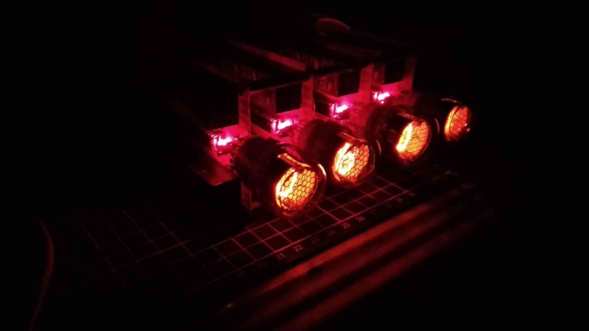
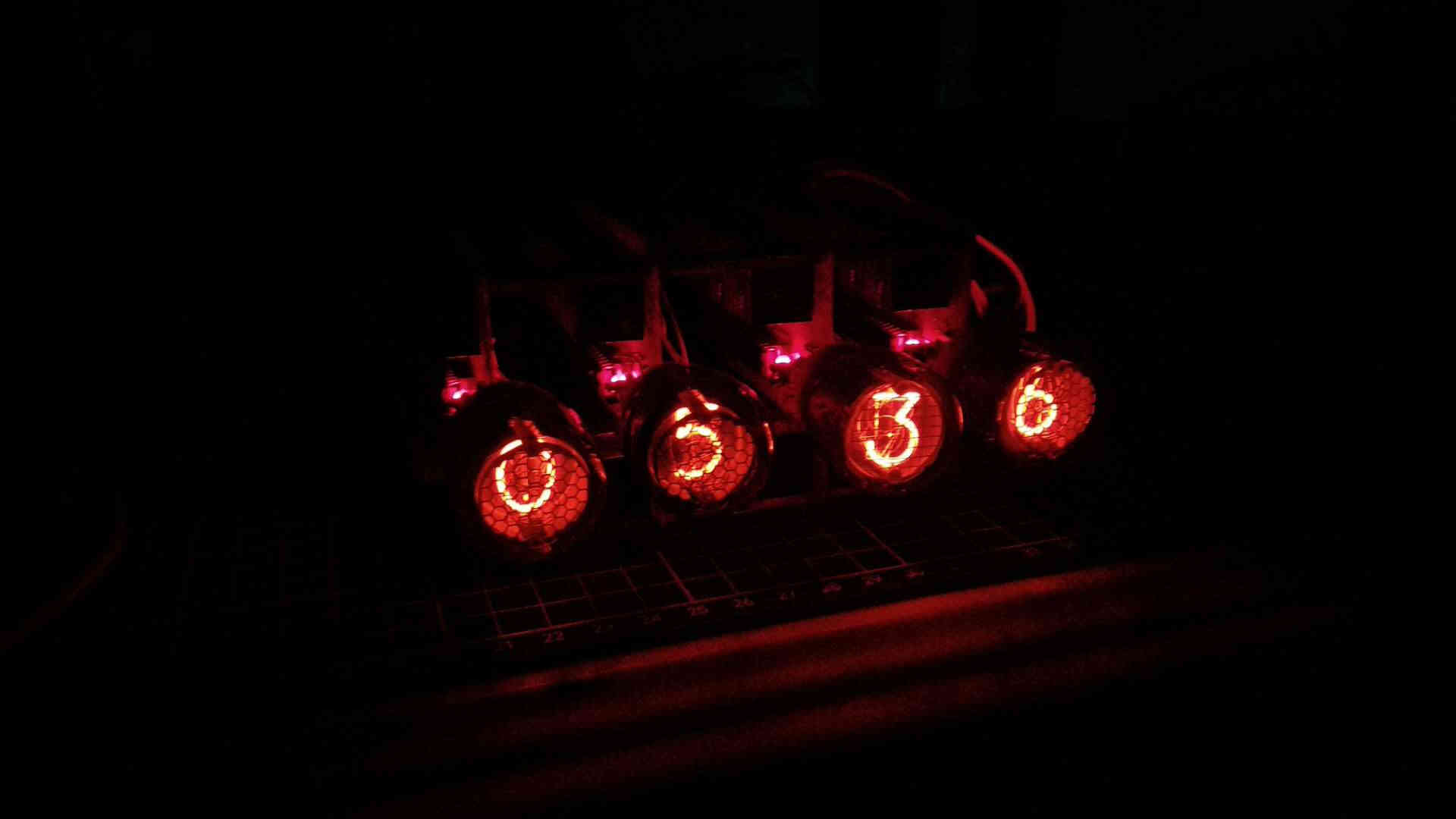
Final Result