Akagi Cosplay Props
This article illustrates how I made my Akagi cosplay props. Most portions of this prop are made from 3/16 inch thickness plywood, cutted using hobby-grade 40W LED laser, then glued and painted. Other portions include 3D printed parts and off-shelf hardwares. All engineering files used to cut the materials are included in this article.
Cosplay, Ship girl, Props, Yumi, Geta, Deck, Quiver, Mast, CAD, Plywood, 3D print, Laser cutting
--by Captdam @ Jun 9, 2026Index
First, let's include a picture of the aircraft carrier Akagi.
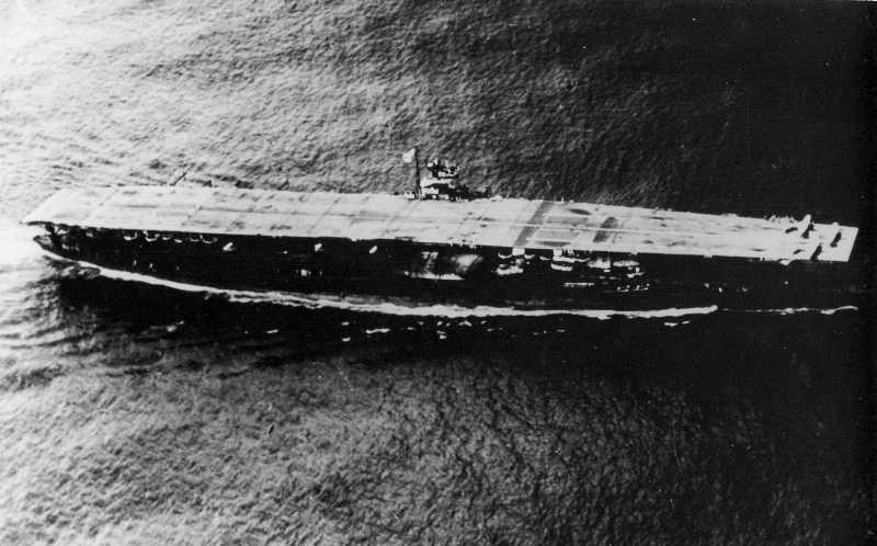
Opps! Not this one. I mean, I am making cosplay props, I want the waifu version of Akagi.
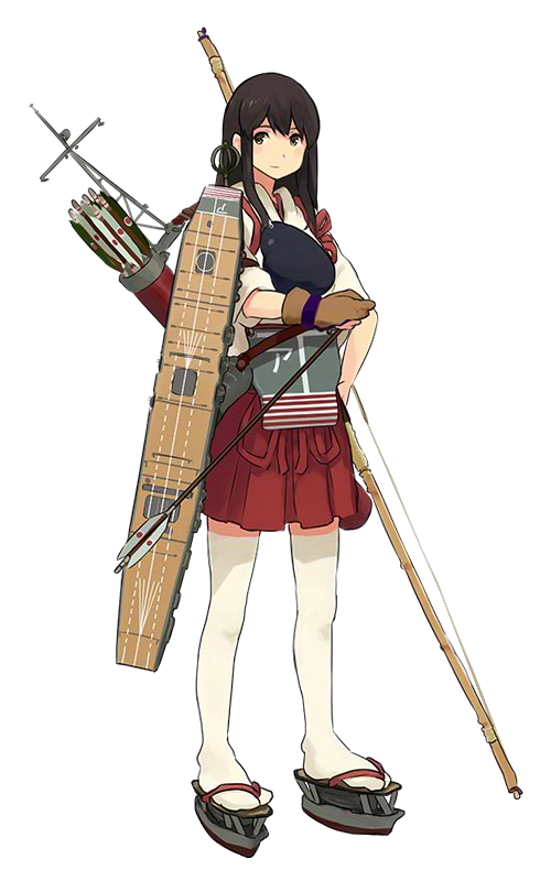
However, the picture of the actual ship can be used for reference because the ship girl character provides little detail.
Deck
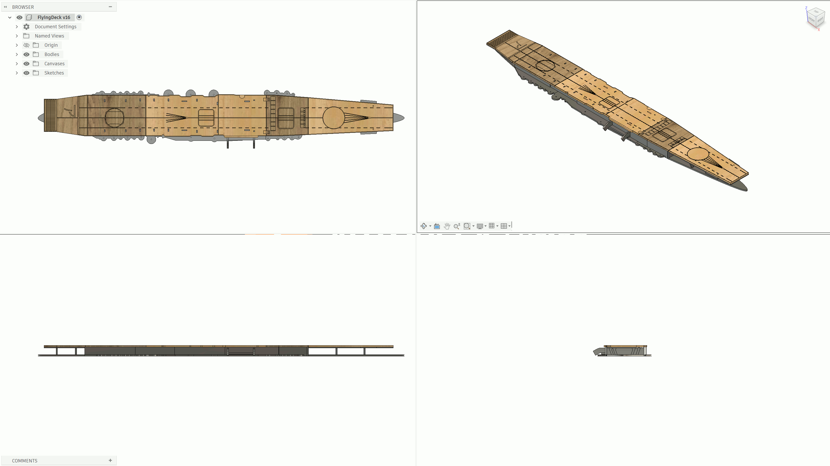
Here is the STEP file for the deck assembly.
As the character shows, the most significant part of the props is the deck on her right arm.
The deck spans from her shoulder to the middle of her leg. If I apply this to my body, it is about 1.1 meters, or 44 inches.
Weird? Ya, in Canada we use both imperial and international for length. We use international unit for height (for example, on our driver's lcense); but imperial for engineering design (because imperial standard parts cost only 1/3 of international standard parts).
Flight Deck
The character provides little detail; therefore, I will be referring to historical photos to create the drawing for the flight deck. Shown in the following screenshot:

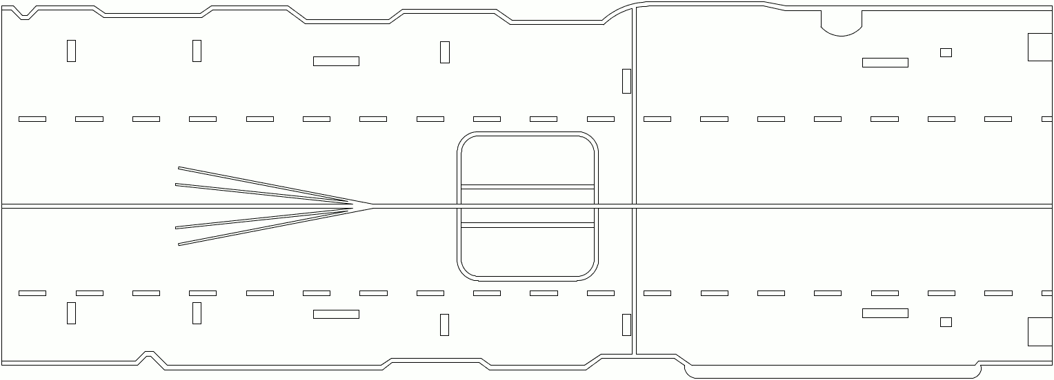
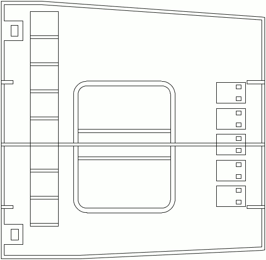
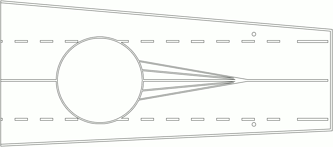
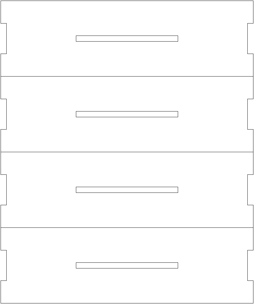
The work area of my laser cutting machine is 400mm x 415mm, or 16in x 16.5in. Therefore, I will partition the flight deck into 4 segments. Shown in the following screenshot:

Note the holes I left on the flight deck. There holes were used to mount the arresting cable. I will not make any arresting cable; instead, these holes will be used as tenon.
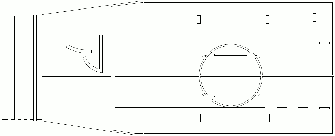
Following are the files for laser cut. All these files are fabricate-ready. You can feed these files to laserGRBL (which recognizes PNG files) and start cutting. All files are in 100 or 300 DPI.
| Segment 4 (Tail) | Segment 3 | Segment 2 | Segment 1 (Head) |
|---|---|---|---|
 |
 |
 |
 |
Cut the outer edge with 24W output power, 2500mm/min speed, 8 passes. (For 3/16 inch thick plywood)
Engrave all lines with 10W output power, 2500mm/min speed, 1 pass. The engrave is used to guide paint in later steps.
Lower Deck
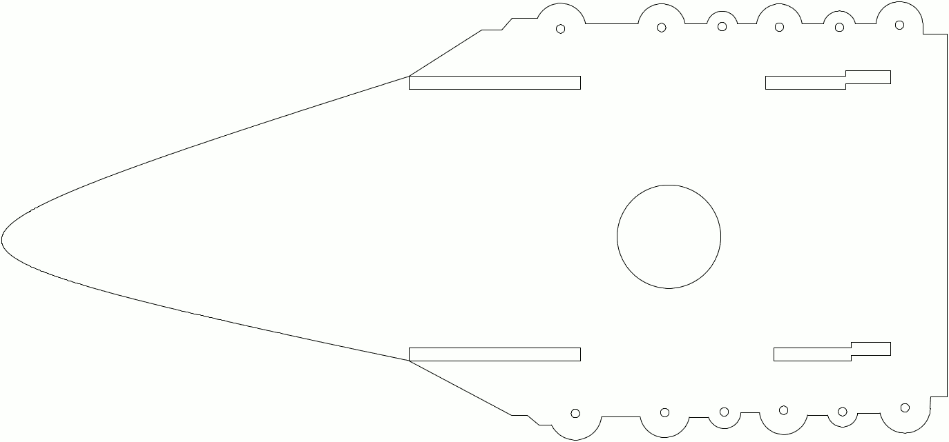
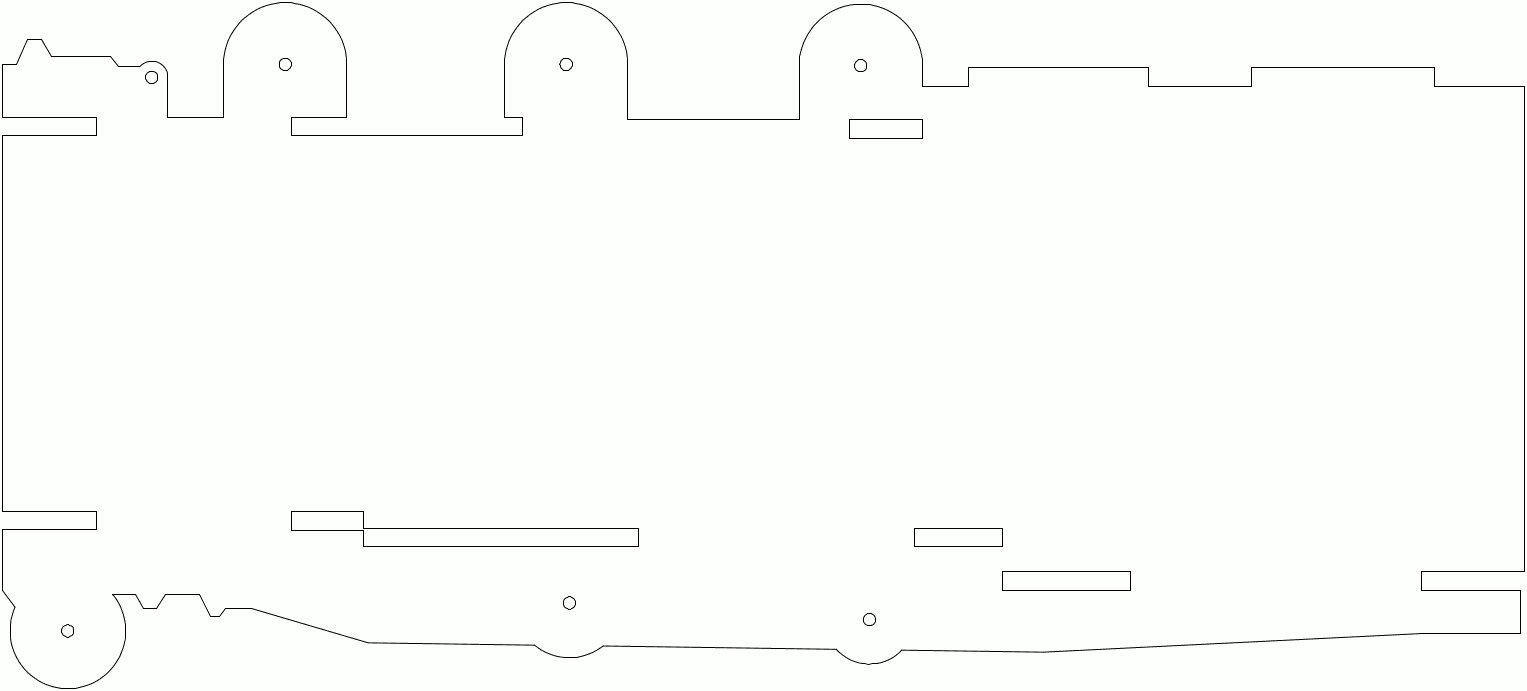
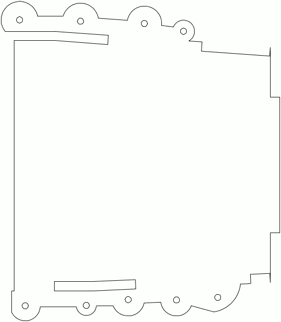
If we zoom in on the character, we can see that the deck not only includes the upper deck (flight deck), but also the lower deck (where the armaments are mounted). Drawing for the lower deck shown below:

The lower deck is partitioned into four pieces. Armaments can be installed on these small, 1/8 inch diameter holes. Furthermore, there is a 1.5 inches diameter hole on the tail section of the lower deck, which is later used to install an adapter that mates the deck prop to my arm.
| Segment 4 | Segment 3 | Segment 2 | Segment 1 |
|---|---|---|---|
 |
 |
 |
 |
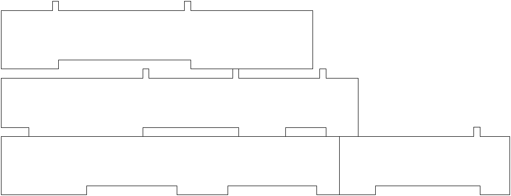
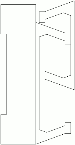
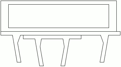
Walls
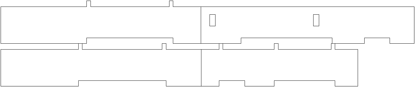
It is not clear how thick (from top side of the flight deck to the bottom side of the lower deck) the deck assembly should be. 1.5 inches looks fine to me.
| Starboard-side | Port-side | Front 1 | Front 2 | Tail |
|---|---|---|---|---|
 |
 |
 |
 |
 |
Under Structure
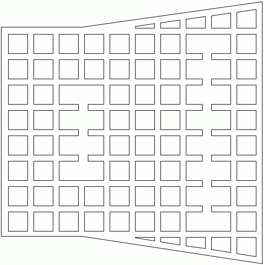
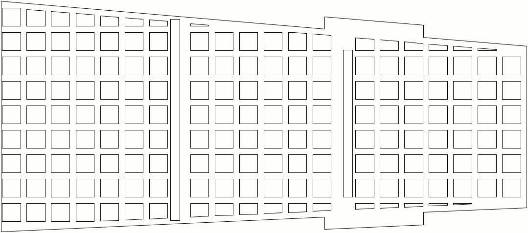
Note the mesh-like structure under the front and tail section of the flight deck. These are used to support the flight deck on the ship. I will use 1/16 inch thick MDF boards for them.
| Tail | Front |
|---|---|
 |
 |
Chinmey
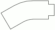
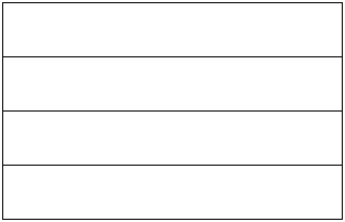
It is not clear to see the chinmey on her deck. I decided to add it.
| Side (Need 2 sets) | Plates (Need 1 set) |
|---|---|
 |
 |
Armaments
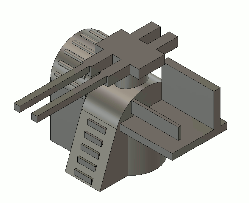
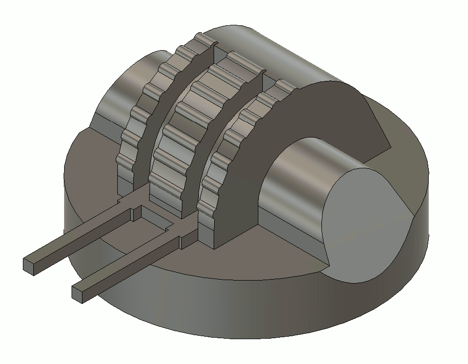
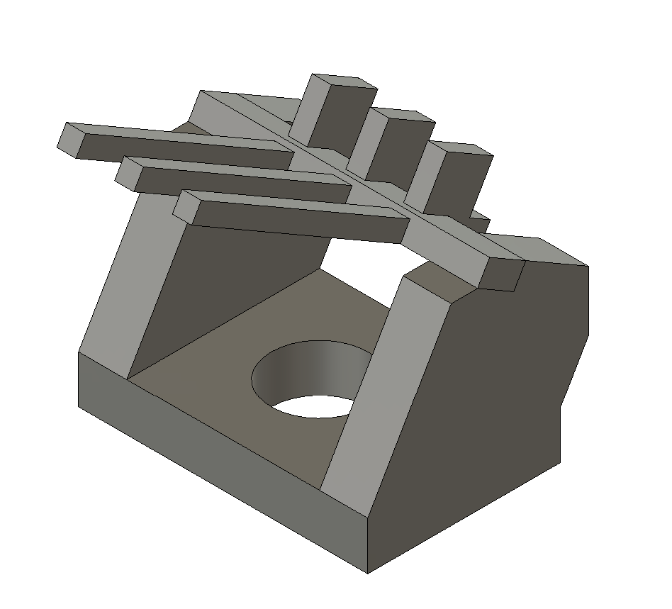
I 3D printed the armaments on the lower deck.
| Opened Gun | Enclosed Gun | AAA | Anchor |
|---|---|---|---|
 |
 |
 |
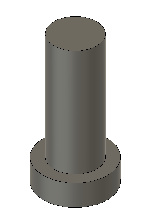 |
| STEP file | STEP file | STEP file | See AA gun |
Use plastic glue to join the guns and their anchor, so, keep them turnable on the wood lower deck.
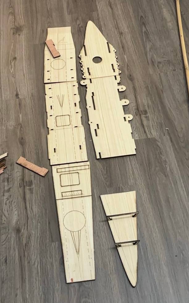
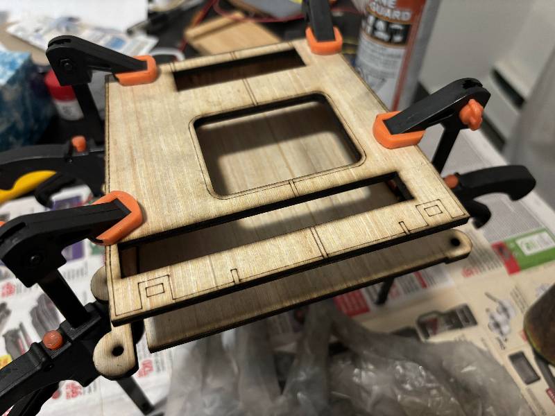
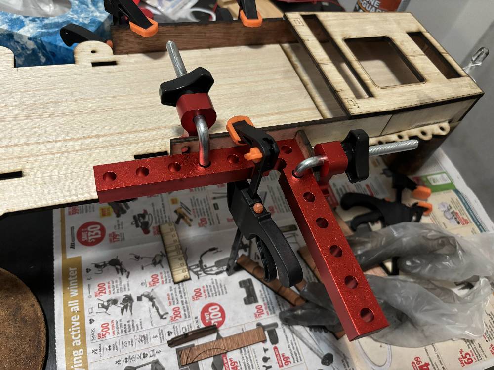
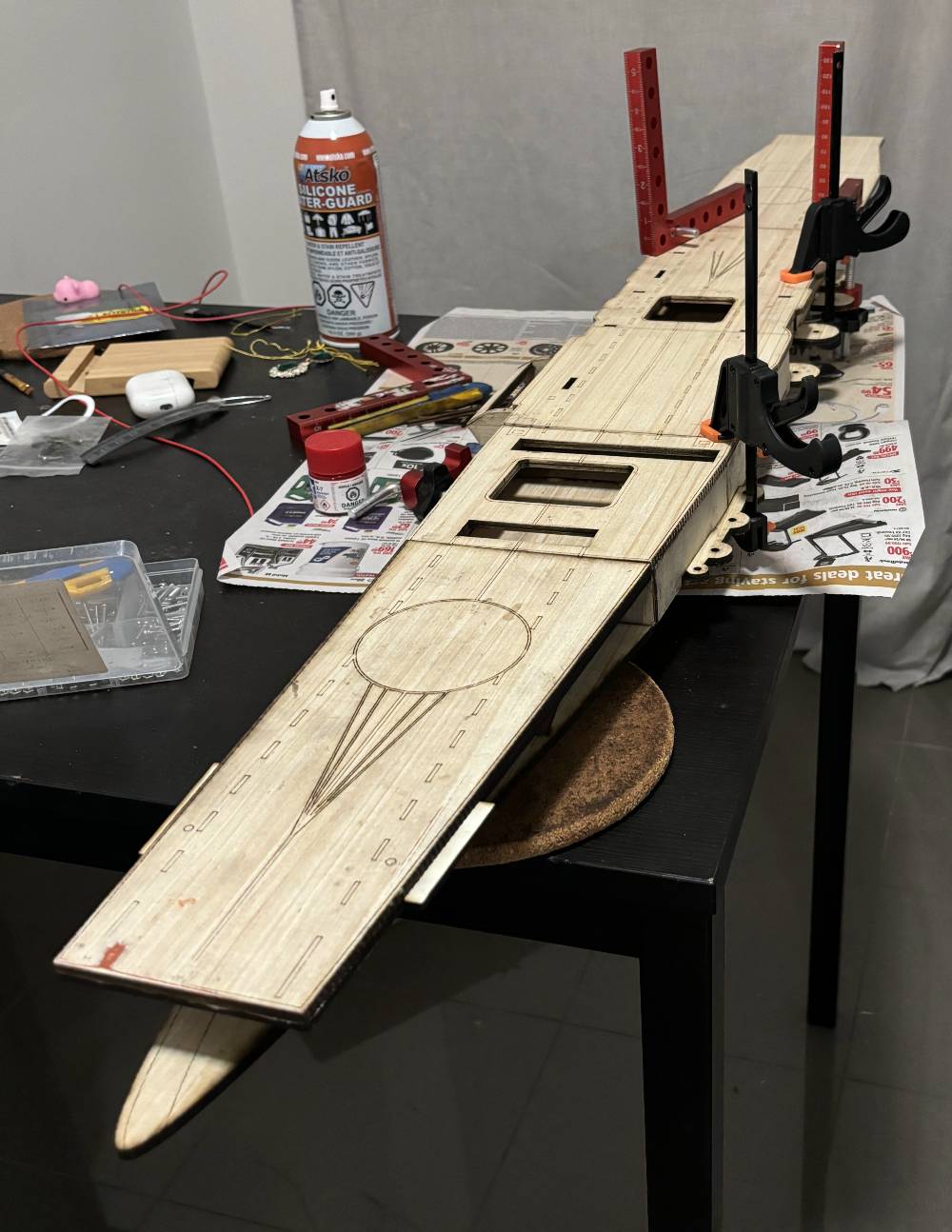
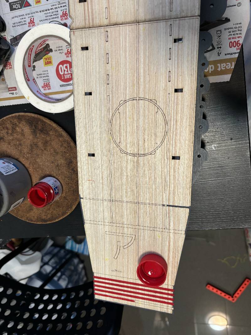
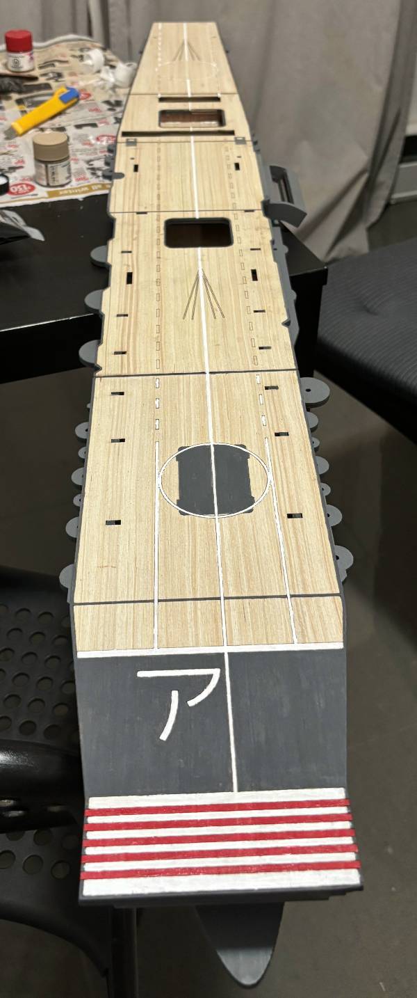
Following are some photos of the work in progress:
| Cut Finished | Glue | Glue | Glue | Paint | Paint |
|---|---|---|---|---|---|
 |
 |
 |
 |
 |
 |
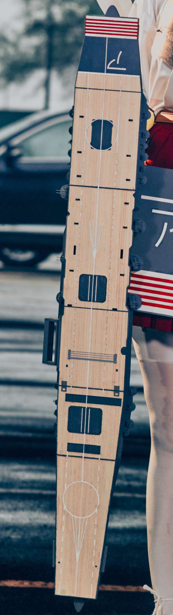
The deck assembly is now finished:
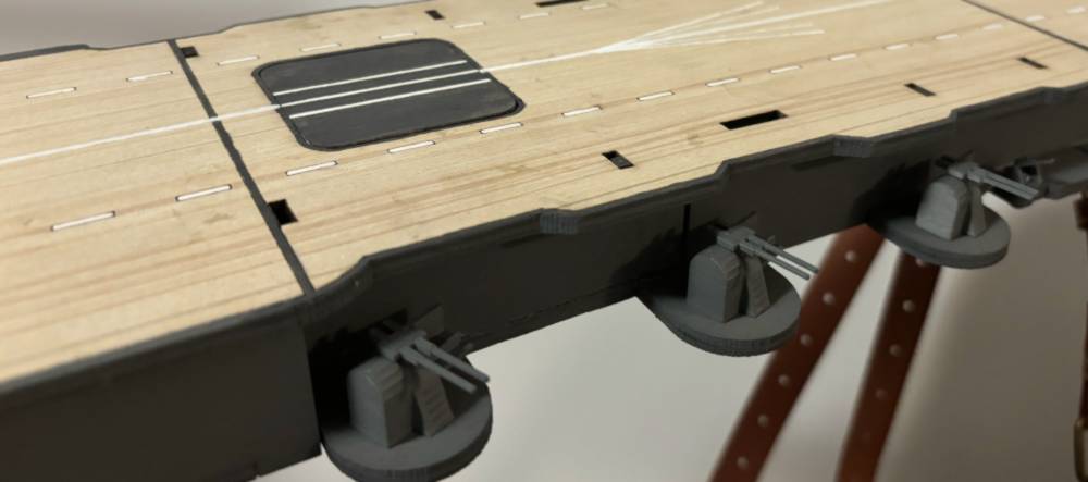
Close up of the armaments:
Adapter
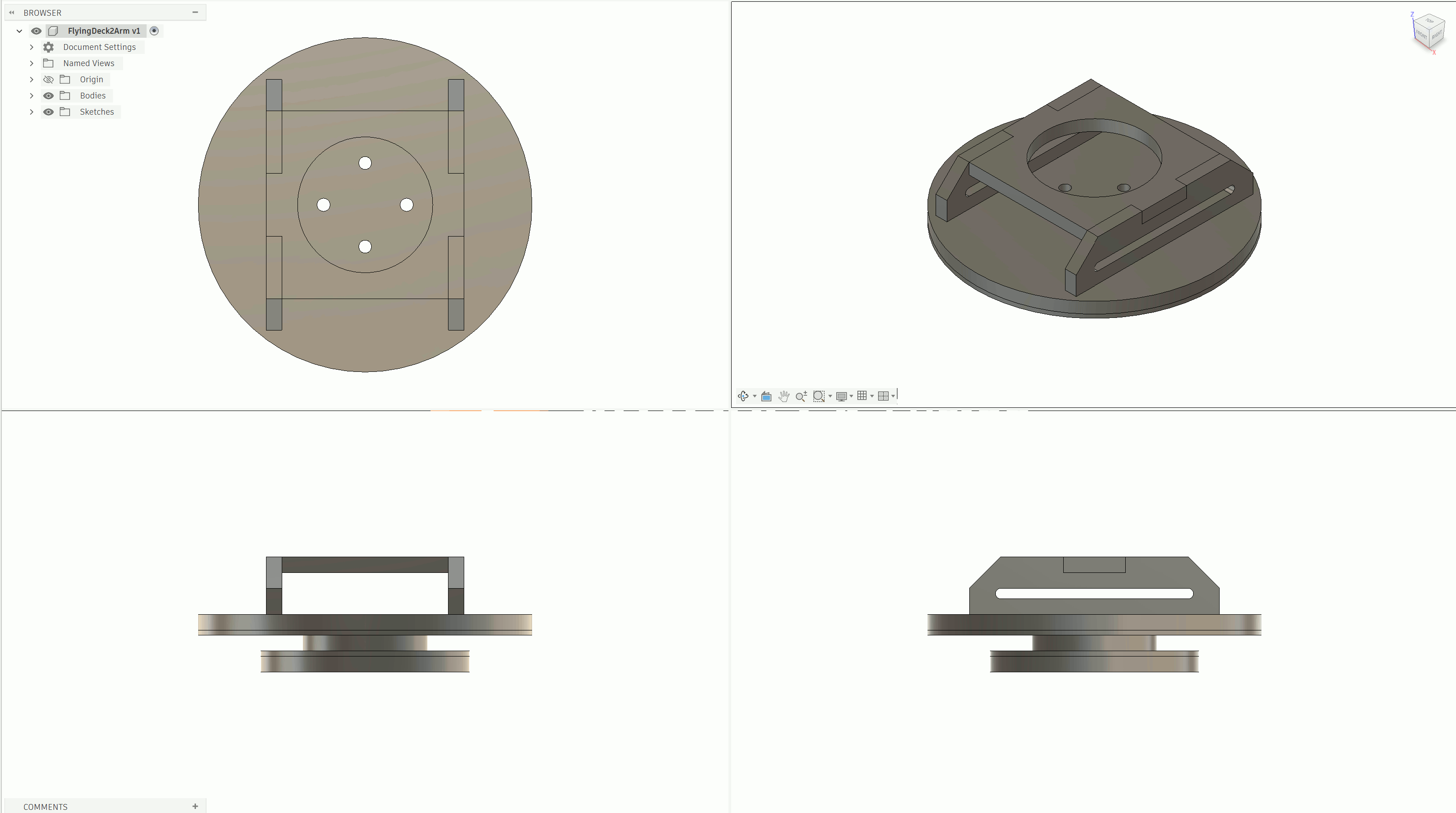
The adapter is used to help mount the deck assembly to the arm.
Following are the files for laser cut. This assembly uses both plywood and MDF. To better illustrate how this structure is made and the purpose of each layer, I will use a table, starting from the top-most layer (arm-side) to the bottom-most layer (deck side). Note the 4 holes on all plates must be aligned.
| Drawing and Cut File | Description |
|---|---|
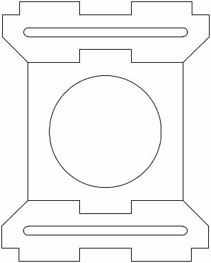 |
On the top is the structure used to band to the coser's arm using two leather belts. The belts will go through the slot on this structure. |
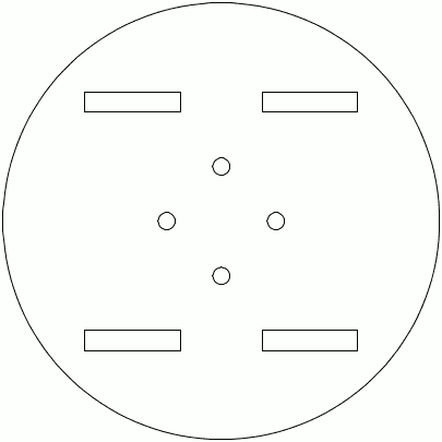 |
A Plywood plate to provide structural integrity. |
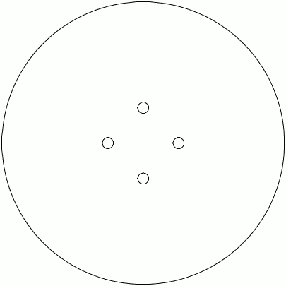 |
A MDF plate to provide a smooth surface between the adapter and the deck. It is recommended to use DMF with paint finished to future reduce the friction. |
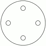 |
A 3/16 inch thick MDF plate acts as a bushing. The difference in material (MDF on adapter assembly vs plywood on deck assembly) reduces the friction between them. Do NOT glue this layer to the next layer. |
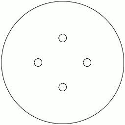 |
A MDF plate to provide a smooth surface between the adapter and the deck. It is recommended to use DMF with paint finished to future reduce the friction. Do NOT glue this layer to the previous layer. |
|
A Plywood plate to provide structural integrity. |
Then, assemble the adapter assembly with the deck assembly using 4 bolts through the 4 holes on the adapter plates:
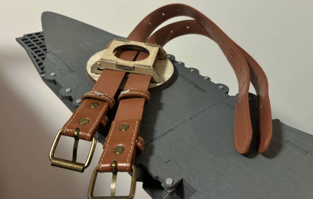
The deck should be turnable.
Apron
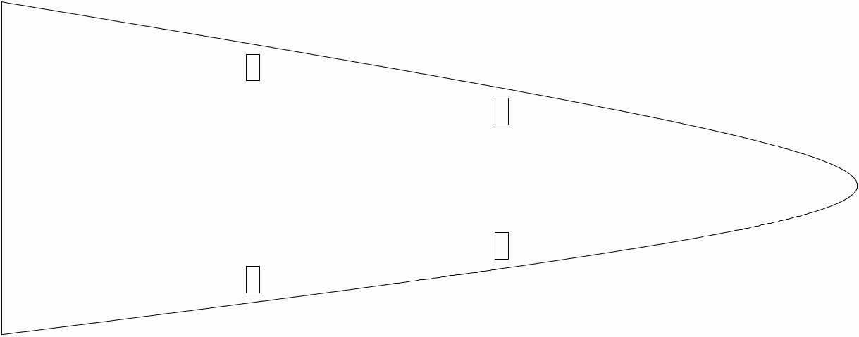
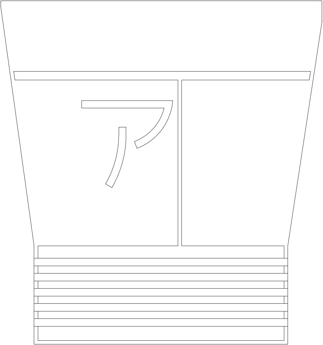
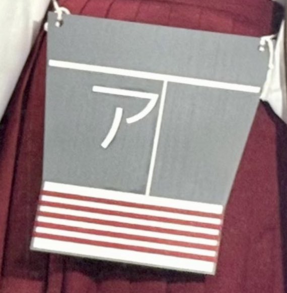
As shown in the character, she wears an apron, which is the tail portion of her flight deck.
I will reuse (but enlarge) the drawing I created for the deck prop.
| Drawing and Cut File | Finished Prop Photo |
|---|---|
 |
 |
Quiver
Quiver Tube
On her back is a quiver with a mast. I am not gonna make the quiver tube; instead, an off-shelf drawing tube solves the problem perfectly:
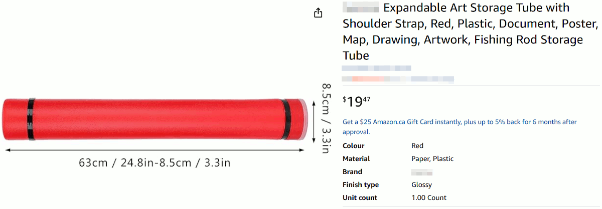
- Its diameter is 3.3 inches, which looks close enough to the quiver on the character.
- Its length is adjustable, from 25 inches to 40 inches.
- It's made from extruded plastic, which is waterproof, light-weight and durable.
- It's red!
- For 20 bucks only.
Mast
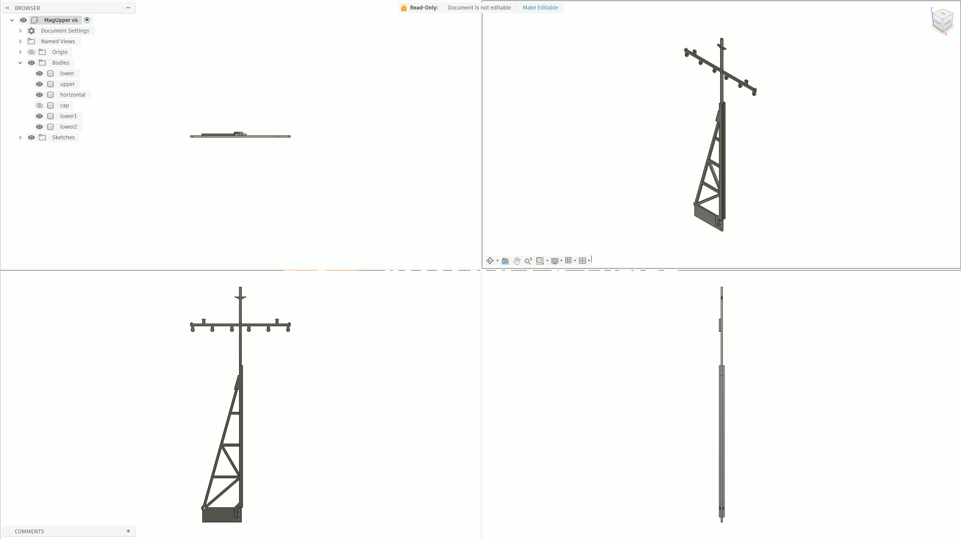
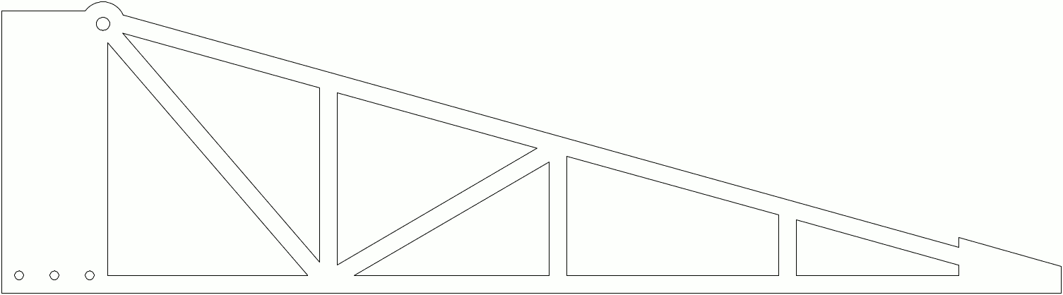
The mast is made from 3/16 inch thick plywood.
| Horizontal Part of Upper Mast | Vertical Part of Upper Mast | Lower Mast | Lower Mast Aux |
|---|---|---|---|
 |
 |
 |
 |
The horizontal part of the upper mast is glued perpendicular to the vertical part of the upper mast. There are 6 pulleys can be used to attach cables.
The upper mast is then glued with the lower mast.
To add more structural strength, two pieces of aux mast are glued on both sides of the lower mast in a sandwich fashion. When cutting the material, it is recommended to cut the part in the perpendicular direction of that when cutting the lower mast.
Note the mast is very thin (1/4-in by 1/4-in cross section), it is prone to break. Be careful when handling, especially when attending anime cons. Maybe it is better to use metal for this part.
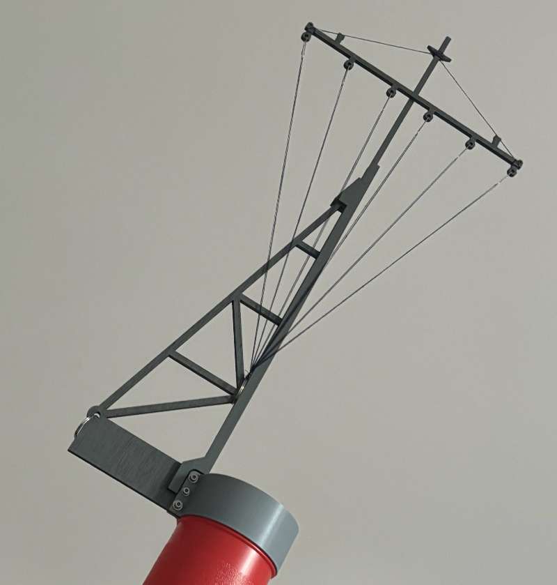
Glue and paint, then attach cables:
Clamp
I decided to use a non-destructive way to join the quiver tube and the mast. In that way, I can reuse the quiver tube for its original purpose, protect drawings from water and other damage when transported. (Yes, I work in the engineering field and I do need to carry drawings outdoors on rainy days for service calls.) I 3D printed two clamps, one on top which fits into the quiver tube's groove, one on the bottom which uses friction. Note the groove on the upper clamp in the section view.
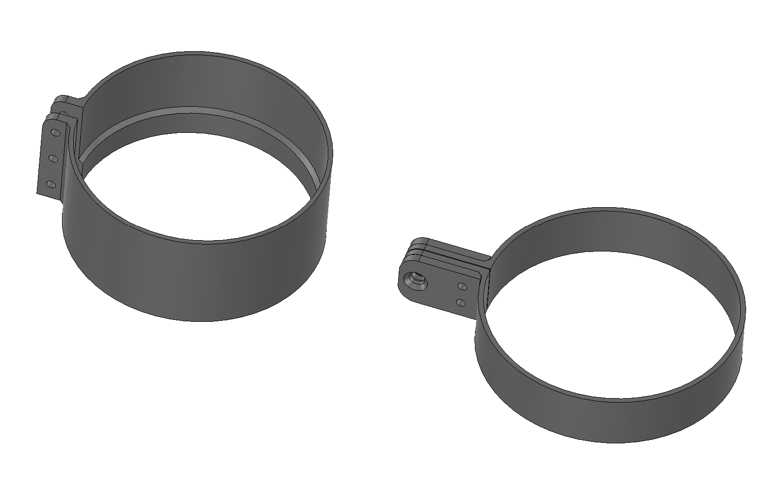
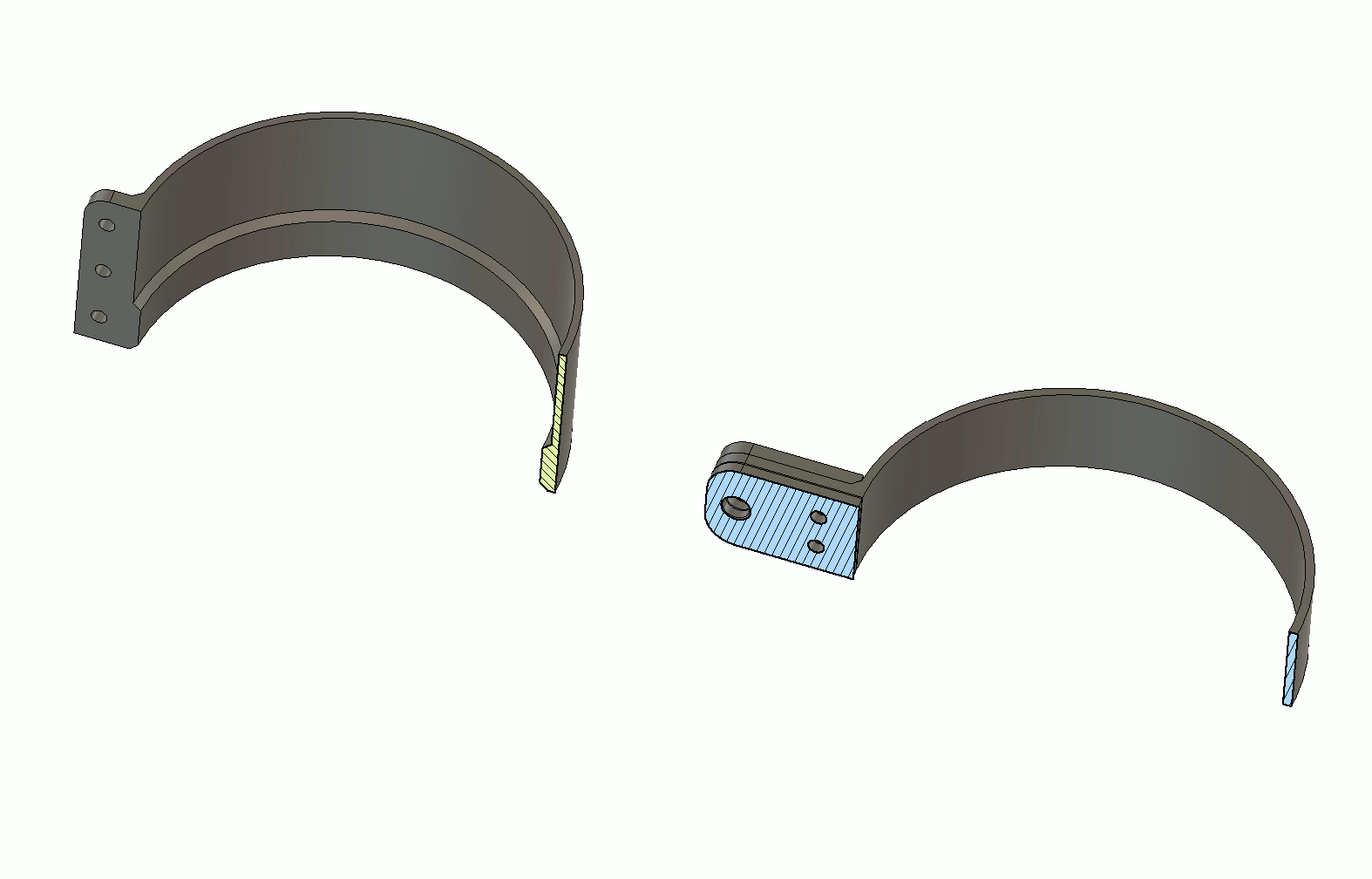
Use 3mm bolts to join the mast and the quiver tube with clamps.
You can export 3D print files for the clamps from the quiver assembly STEP files.
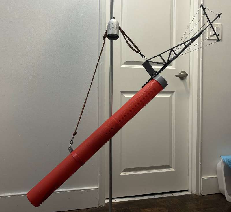
Attache a leather belt to the upper and lower clamps. The finished quiver assembly is shown below:
Shoes (Geta, Wooden Clogs)
Her shoes are not simple geta (wooden clogs); instead, they mimic the shape of the ship hull.
Generally speaking, a ship hull is made from a continuous, curved surface. It is favored to 3D print this prop because 3D printers are capable of making curved models. However, my 3D printer is not large enough to handle something as big as a shoe (that is, around 25cm). Furthermore, it is questionable whether a 3D printed (PLA) shoe is durable enough to my body weight (that is, 60+ kg with all props), especially since I will need to wear it and walk for a long time during a con.
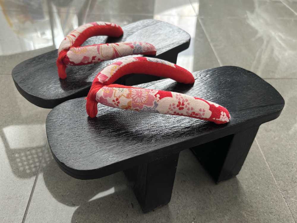
I decided to modify a pair of off-shelf geta. This pair of geta are in black color with red straps, which is the same as what the character wears. What I add on the geta is an outer wall mimicking the ship hull. In this case, the geta handles all the structural load, the hull-shape outer wall takes care of the appearance.
The geta I found has very high teeth. It is about 4-1/4 inches from floor to the top. It is much higher than most geta; therefore, wearing it is challenging. However, it looks more aesthetic.
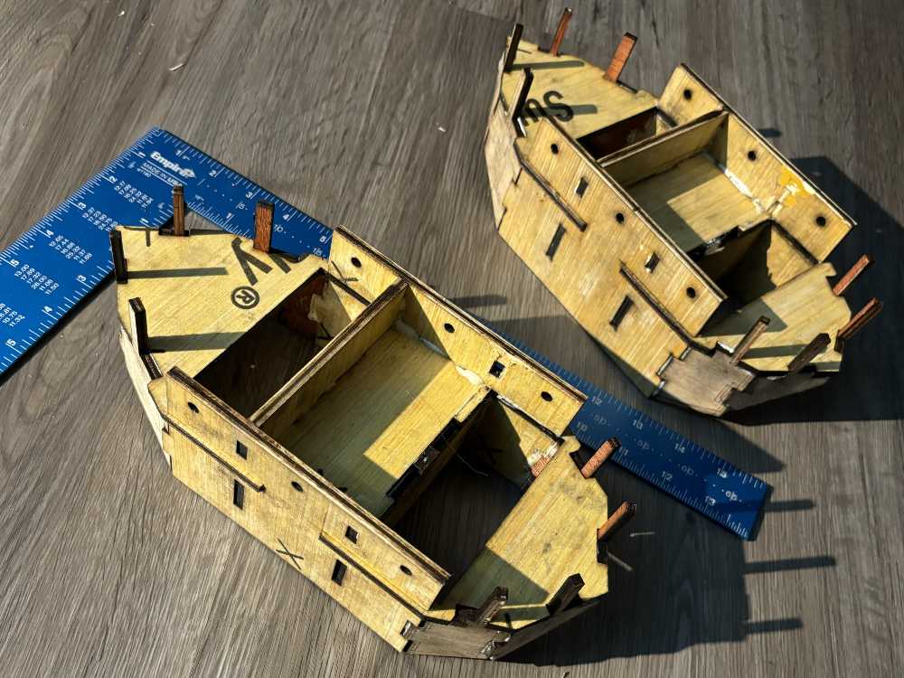
I divided the hull into 5 discrete pieces, shown in the following drawing. Furthermore, the hull-shape wall is not directly glued to the geta, but to the inner core and cross bone. The core and bone are attached to the geta's teeth by friction. In other words, I can remove the hull from the geta and use the geta for other cosplay.
| Inner Core (Need 2 sets) | Cross Bone (Need 2 sets) | Outer Wall (Need 4 sets) |
|---|---|---|
 |
 |
 |
Geta is hand-made. In other words, they differ in dimension. (Even for the same pair of geta, there are a few milimeters of difference in dimension between the left geta and the right geta.) The drawings are created based on measurement of this specific geta.
Cut the panels and gule them together:
Following is a photo of the finished geta assembly, taken during an anime con:
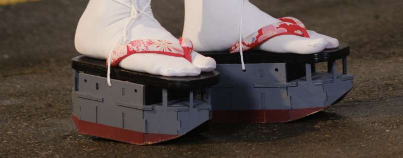
I secure the geta with my feet with cotton string to prevent falling during the con.
On the con, no one realized there is an off-shelf geta hiding inside.
Purse
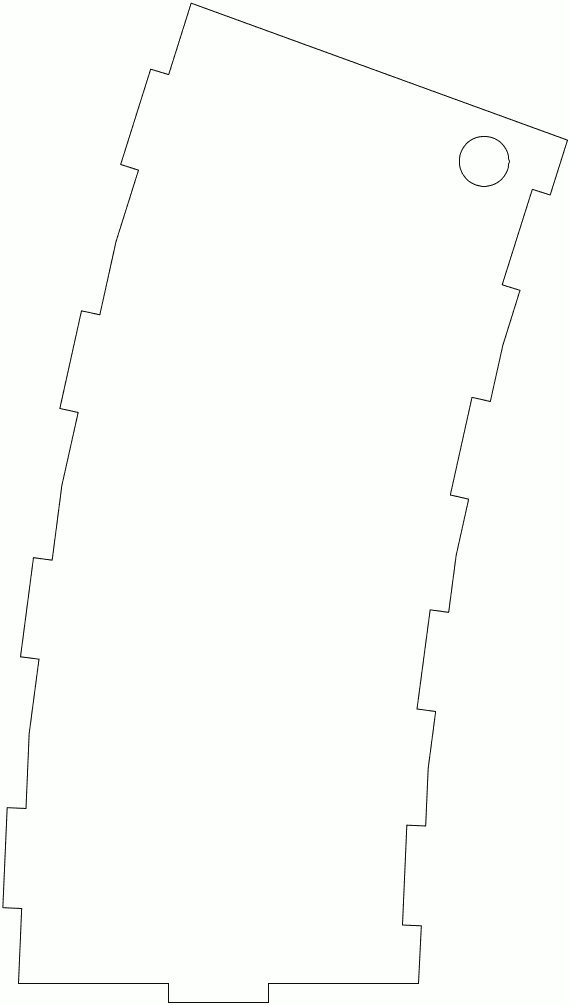
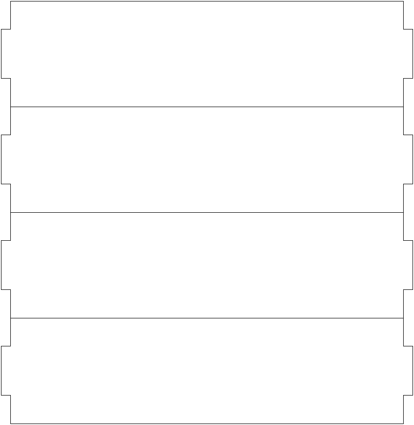
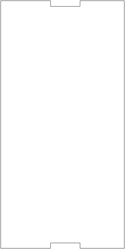
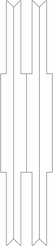
This may be the most overlooked prop. The purse mimics the chimney on the ship. Following are the drawing and cut files:
| Side Panel (Need 2 sets) | Inner Panel (Need 1 set) | Outer Panel (Need 1 set) | Bottom Panel (Need 1 set) | Rib on Outer Panel (Need 1 set) |
|---|---|---|---|---|
 |
 |
 |
 |
 |
Paint the upper portion of the purse in grey and the lower portion in black, then attach a leather belt. The finished prop is shown below:

Yumi (Bow)
A real yumi (japanese bow) is expensive, and requires routine maintenance. Furthermore, a real yumi is a real weapon, making it prohibited for most cons.
An alternative is to use PVC pipes. It is cheap, requires no maintenance, easy to source and can be reformed after heat up. Furthermore, it is flexible; that means, you can draw the PVC pipe yumi for pose. On the other hand, it provides little draw weight, making it a safe option.
Yumi is long. It is even taller than the archer. For easy transport, I cut the PVC pipe yumi into two sections at the grip. Then, I use a PVC pipe fitting (coupler) to join them. The pipe fitting works by friction without using any glue. So, I can assemble them when used and disassemble them when transported.
I used the following figure as reference to make the yumi:
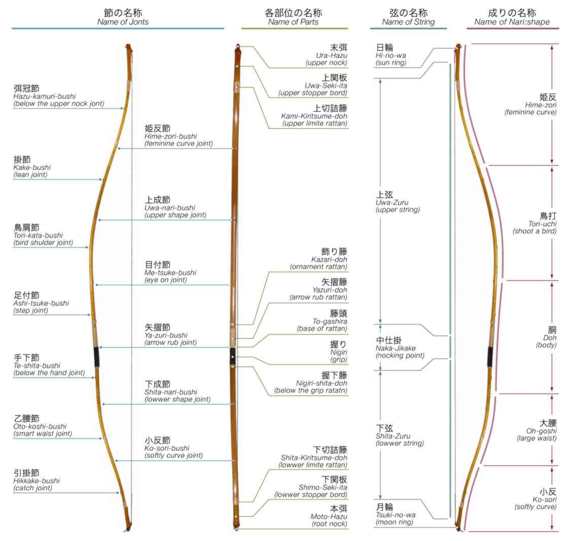
I used 1/2 inch Sch 40 PVC pipe for this project. It's outer diameter is about 2cm. The overall length is 2.2 meters (So, you buy one length of PVC pipe from a hardware store to make the yumi, a length is a full 10 feet piece). Note the lower portion of the yumi is shorter than the upper portion:
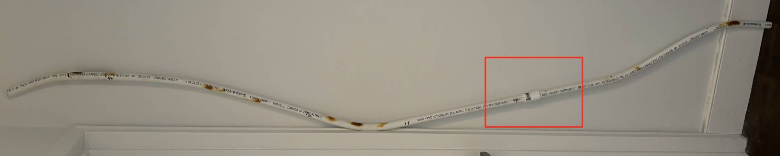
Then, I used a propane torch to heat the PVC pipe when forming it into the bow shape. I accidentally found out that, when the PVC pipe overheated (or ignited), its color turned brownlish. This brownlish color provides a perfect texture that mimics wood or bamboo. Then, I lightly sand the pipe to remove the carbon deposit but leave the browned plastic surface.
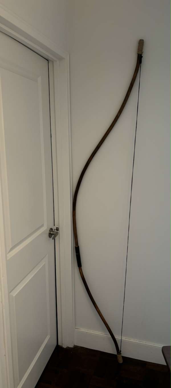
Wind white cotton string on the grip and both ends of the yumi. The yumi is now finished.
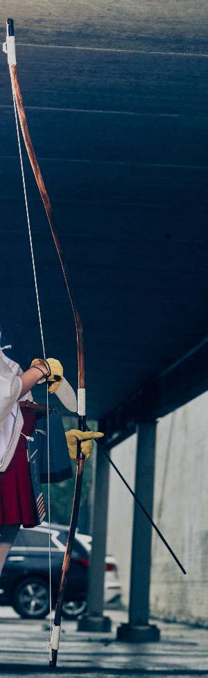
Everyone thought this is a real wood yumi, until I show the lightly-covered pipe marking.
Cosplay
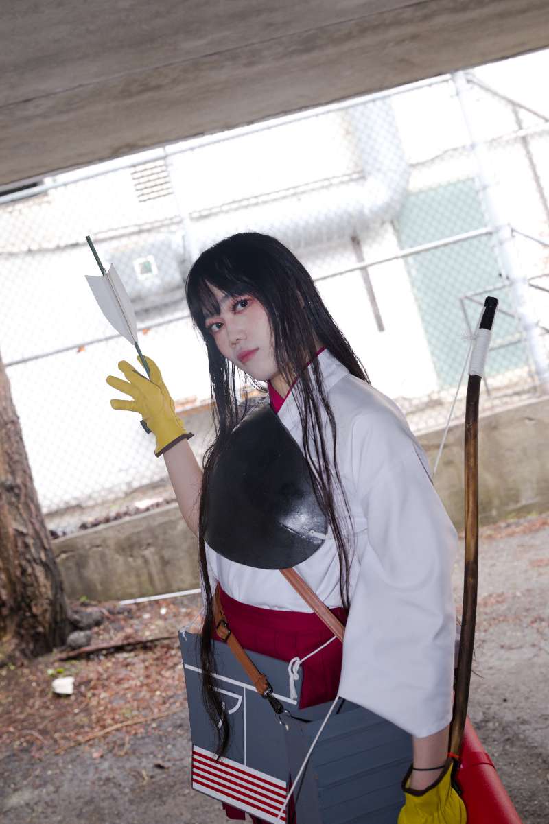
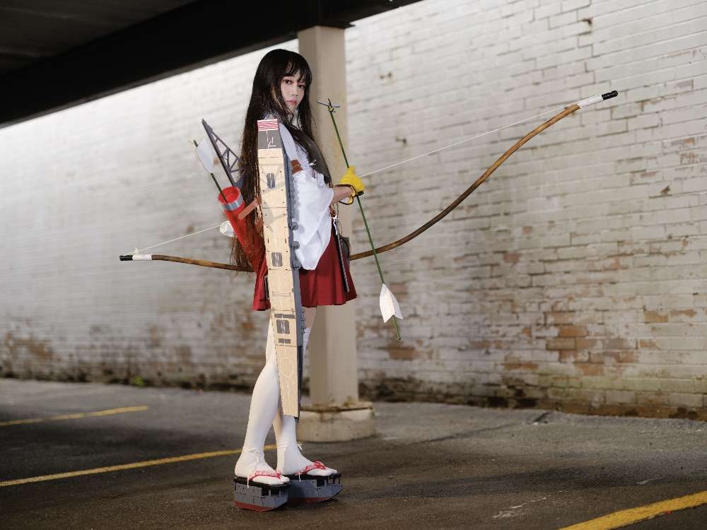
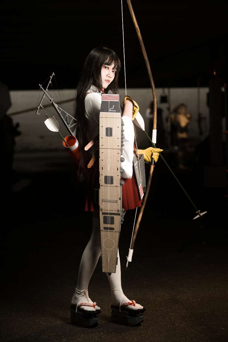
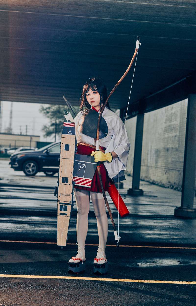
Following are some photos taken on Anime North 2026:
All photos are copyright protected, reupload and redistribute prohibited. However, you are free to share other portion of this article under CC BY-SA.