MSC-51 and ultrasonic sensor
Distance measure using HC-SR04 ultrasonic sensor and MSC-51 MCU in assembly language.
ultrasonic sensor, distance measure, MCU, a51, assembly, MSC-51
--by Captdam @ Dec 20, 2018Purpose
A ultrasonic sensor is used to measure the distance using ultrasonic.
I just found this sensor from my storage. I got it few year ago but has not get a chance to play it. Resently I am working on a project implementing MPU-6500, and I find I may implement this ultrasonic sensor into this project.
So, this is how this work. A PC will query the MCU using UART, the MCU then query the sensor. The sensor will take a while to measure the distance.
Ultrasonic sensor module
The ultrasonic sensor I have is HC-SR04. It has 4 pins, VCC (5V power), Trigger, Echo and GND.
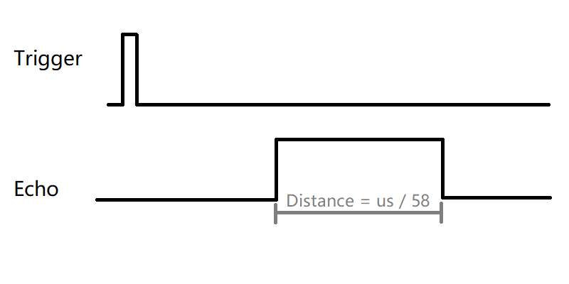
To measure the distance, we need to pull the Trigger pin high for at leaste 10us (althrough 8us is sufficient when I test it, but let's just follow the datasheet's recommendation).
Then, the speaker on the module will send 8 40kHz pluse. The sound wave travels from the speaker of the module, hit some object, then return to the module.
When the module receive the return wave, it pulls the Echo pin high for the same amount of time as the sound wave trave from the speaker to the object and return to the module. In another word, the Echo pin will be high for double of the time of the sound wave travel between the module and the object.

t = 2 * d / v
d = t * v / 2 = t * 170m/s
Sound of speed is 340m/s
The MCU I used is STC89C52RC, an Intel8051 architecture MCU. The external crystal is running at 12MHz, and the MCU takes 12 external cycles every tick. Therefore, every MCU cycle takes 1us. So, the distance (in cm) = cycle count / 58.
BTW, it looks like HC-SR04 is a very popular module. There are tons of HC-SR04 ultrasonic sensor module available on the market. Different manufactures seem like sharing the same manual, they all get the same content except the logo on the cover page. 90% of the manuals mistakely sate the frequency of the ultrasonic wave is 40Hz.
MCU system design
First of all, let's connect the module to the MCU. According to the datasheet, there are 4 wires, two for power and two for signal.
To measure the distance from the module to the object, the key is to measure the time that the Echo pin is high. In this project, I will use Time2 of the MCU to measure the time. Port1.2 of the MCU is connected to the Trigger pin of the ultrasonic sensor. To start the measurement, the MCU drive this pin high for 10us. Port1.1 of the MCU is connected to the Echo pin of the module. The advantage of using Port1.1 is that, Port1.1 is multiplexed with T2EX, which is external trigger of MCU Timer2. When the ultrasonic module's echo ends, falling edge on this pin will cause the timer hardware to stop Timer2 automatically and issue an interrupt. The CPU of the MCU doest not need to constantly monitering the pin; hence the CPU can concentrate on other tasks.
The datasheet state that the maximum range of this module is 4m. Because the speed of sound is 340m/s, it takes 23200us for the ultrasonic wave to travel from the sensor to the object and then return. For a 12T 8051 MCU with 12MHz external crystal, the CPU is running at 1cycle pre micro second. 23200us means 23200 cycles. To hold this number, a 14.50 bits counter is requires ( log2(23200) = 14.50 ). Fortunately, Timer2 of the MCU is 16 bits wide, it can hlod this number without any issue.