Understanding MODBUS RTU
Introduction to MODBUS and MODBUS RTU protocol. This blog presents the format of MODBUS RTU packet, including the request from master to slave and the response form slave to master. This blog also shows how to ccompute the CRC-16 value for MODBUS packet in AVR assembly language.
MODBUS, MODBUS RTU, PLC, serial, industry control, CRC
--by Captdam @ Aug 20, 2023Introduction
Recently, I was working on a project that reads data from PLC and manipulates the data using my custom designed hardware.
My first thought was to use the RS-232 / RS-485 port of the PLC to implement a custom protocol. For example, when I send 0x01 to the PLC, the PLC should return a packet as the result of function 1; when I send 0x02 to the PLC, the PLC should return a packet as the result of function 2.
When reading the manual for that PLC, I cannot find too much detail about how to receive and send data through the serial port (RS-232 or RS-485). However, the term “MODBUS” in the manual pops-up and get my attention.
After some reaching about the “MODBUS” on Wikipedia and on the MODBUS website, I realized that “MODBUS” is exactly the diamond I was looking for. The serial version of MODBUS (MODBUS RTU, which stands for MODBUS Remote Terminal Unit) was developed in 1979 by Modicon (now Schneider) is a very elegant protocol and it is a de facto standard in PLCs and other industry devices. Furthermore, this is a royalty-free protocol.
It is elegant because the protocol defined a simple and compact packet format. MODBUS RTU packet has three segments:
A 1-byte long address.
Variable length of packet payload.
A 2-byte long CRC checksum.
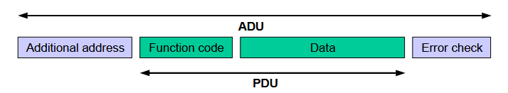
The total length of a packet (ADU, Application Data Unit) includes the address, the payload and the checksum. And it must be less than or equal to 256 bytes. Since the address is 1-byte long and the checksum is 2-byte long, the maximum length of the payload (PDU, Protocol Data Unit) is 253 bytes.
For multi-byte data, the MODBUS requires the implementation to send high-byte first. For example, to send a 16-bit integer 0x1234, 0x12 first, then 0x34.
We can arrange a 256-byte block aligned to 256-byte page to store the packet in our Tx buffer. For a typical 8-bit MCU (microcontroller) like AVR or 8015 XRAM, we can use a 16-bit pointer with fixed high-byte. For micro-optimization, we can start the transmission after setting the Tx buffer pointer. We increase the low-byte of this pointer at each Tx interrupt and stops when the low-byte is zero. We know, single-byte comparison is way easier than multi-byte comparison in 8-bit world. See implementation code for detail.
ELEGANT! ELEGANT!!!
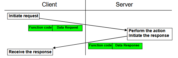
MODBUS RTU is a request-response protocol like some of the other common protocols. The master sends a request packet to a specific slave device, then the addressed slave device returns the request data to the master. The master Tx is connected to Rx of all slaves and all slaves’ Tx are connected together with the master’s Rx.
A transmission can be divided into two steps:
Master sends a request.
The addressed slave processes the request and returns a response.
Of course, both the master and slaves perform packet check to verify the transmission integrity. The master also has a timeout and retry mechanism in case of the packet is lost during the transmission.
Both the request and response packet have the address segment and the checksum segment. The payload section is different.
Because a single-data read/write is equivalent to a multi-data read/write with length of 1. If we want to go extreme on the bandwidth control, we can implement the single-data read/write as well. In this article, we will only discuss the concepts of multi-data read/write. More detail can be found in the MODBUS Specification.
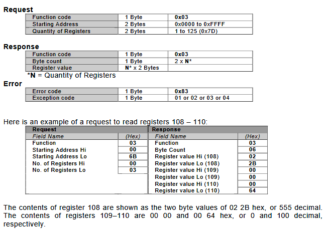
For a read process:
The request on the master-side: the payload has a 1-byte long function code; followed by a 2-byte long start address of the data in slave's memory; followed by a 2-byte long length of data to read (note, this is the number of data elements not the length in bytes).
The response on the salve-side: the payload has a 1-byte long function code, same as the function code in the request; followed by a 1-byte long length of data (note this number is the length of data in bytes); followed by a string of data in interest.
For a write process:
The request on the master-side: the payload has a 1-byte long function code; followed by a 2-byte long start address of the data in slave's memory; followed by a 2-byte long length of data to write (note, this is the number of data elements not the length in bytes); followed by a 1-byte long length of data (this time in unit of bytes); followed by variable length of data to write.
The response on the salve-side: the payload has a 1-byte long function code, same as the function code in the request; followed by a 2-byte long address of data in slave's memory; followed by a 2-byte long length of data to write (note, this is the number of data elements not the length in bytes).
The MODBUS protocol was designed in 1979, it deses not cover fancy functionality found in some more modern protocols. However, my application only requires read basic data from PLC, MODBUS is good enough for my requirement.
Bench Study
People says don't build a wheel; but sometimes reading other libraries actually cost more time than develop your own. Plus, you learn what happened, you have full control, and you know where to look during debugging.
Probably one of the best ways to inspect the MODBUS packet is to let the PLC to send a request to a computer to analysis request packet format; then return that same packet (or flip some bits to simulate a transmission error) to the PLC and see what happen on the PLC.
Enable MODBUS on PLC
First. Let's configurate the PLC to enable the MODBUS functionality.
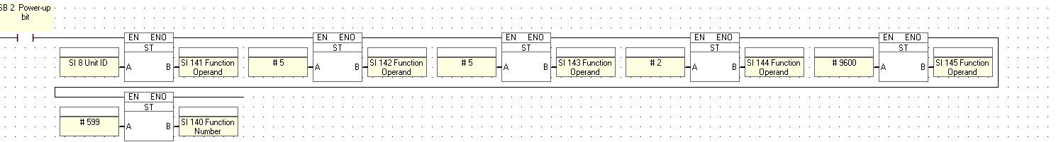
This ladder setup the PLC to use MODBUS on the serial communication port at 9600 BAUD. It also sets the slave ID for this PLC to receive request. It defines the retey, delay and timeout value for this PLC when sending request.
View Request Packet
Because we have no idea how a MODBUS packet will look like. We will write a program in our PLC to send a “Read registers” request to our computer. Of course, our computer will not return anything. All we need to know in this step is what the response looks like, and we don't care what the response will be and what the PLC will do in case of no response.
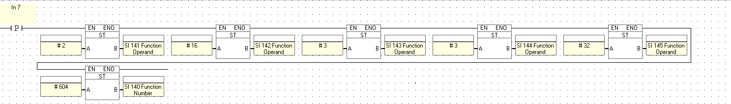
This ladder let the PLC to send a Read registers command to read 3 registers from slave 2, starting at address 16, save to address 32 in the PLC at the rising edge of Input pin 7.
The following data are placed on the bus:
0x02 0x03 0x00 0x10 0x00 0x03 0x04 0x3D
Because the MODBUS sends high-byte first for multi-byte data, the above packet can be read as:
-
0x02: Slave ID
-
0x03: Function code = Read registers
-
0x0010: Start address = 16
-
0x0003: Length of data = 3 data
-
0x043D: Checksum = 0x3D40
View Response Packet (No Error)
Now, we have a valid request packet, we can echo this request back to the PLC to read registers on the PLC.
Let's send the above request to the PLC, we get the packet:
0x02 0x03 0x06 0x30 0x39 0x00 0xF4 0x00 0xF3 0xAD 0xC7
where:
-
0x02: Slave ID
-
0x03: Function code = Read registers
-
0x06: Length of data = 6 bytes
-
0x3039: Data in register 16 = 12345
-
0x00F4: Data in register 17 = 0x00F4
-
0x00F3: Data in register 18 = 0x00F3
-
0xADC7: Checksum = 0xC7AD
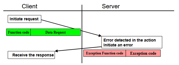
View Response Packet (Error in Packet)
Let's re-send the above request to the PLC, but with some bit flipped, we get a packet indicating checksum error:
0x02 0x03 0x01 0x70 0xF0
where:
-
0x02: Slave ID
-
0x03: Function code = Read registers
-
0x01: Error code = 01
-
0x70F0: Checksum = 0xF070
Specification
Let's now verify what we found the experiment with the MODBUS Specification.
Timing
Now, we have studied that MODBUS response contains a byte indicating the length of the packet. Using this data can help us determine the end of the packet (in another word, when to stop receiving and process to next step).
However, we still facing two issues:
-
What if the slave is offline or the UART bus brake, causing we receiving no response?
-
What if the byte representing packet length is corrupted?
These issues will cause our program to enter a dead waiting loop.
Another solution is to set a watchdog timer. At timeout, we determine the slave is offline or the packet is end. In the MODBUS spec, the space between two packet should be greater than the time to send 3.5 characters.
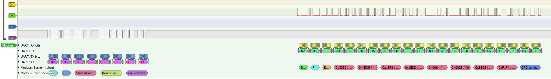
Above figure shows a MODBUS transaction. In this figure, the bus is set to 19200 BAUD. As we can see, the slave spends about 20 characters of time to response. We measured the space is about 12ms long. On the other hand, the space between two characters in the same packet is about 1 to 2 bits.
Therefore, we will need 2 watchdog timers.
-
Watchdog 1: Response timeout. MODBUS spec did not mention about this time, we need to check the response time of the salve dvice and perform some tests.
-
Watchdog 2: End of packet. We can set this timer to the time to send 3.5 characters.
CRC Compute
MODBUS RTU is a very basic data read/write protocol. It is quite easy to understant the packet format; the only challenge involved is to compute the CRC checksum.
MODBUS RTU uses Initial value of 0xFFFF with Polynomial of 0xA001. The AVR GCC provides a ready-to-us lib for us. There are also tons of tutorial about CRC compute available online. Consider the following C code for AVR embedded system:
#include <avr/io.h>
#include <avr/interrupt.h>

volatile uint8_t modbus_buf[256] __attribute__ ((aligned(256)));

int main(void) {
	// Init
	modbus_buf[0xF8] = 0x02;
	modbus_buf[0xF9] = 0x03;
	modbus_buf[0xFA] = 0x00;
	modbus_buf[0xFB] = 0x10;
	modbus_buf[0xFC] = 0x00;
	modbus_buf[0xFD] = 0x03;
	modbus_buf[0xFE] = 0x04;
	modbus_buf[0xFF] = 0x3D;

	// Process
	uint16_t val = 0xFFFF;
	for (volatile uint8_t* ptr = modbus_buf + 0xF8; ptr < modbus_buf + 0x100; ptr++) {
		val ^= *ptr;
		for (uint8_t i = 0; i < 8; i++) {
			if (val & 0x0001) {
				val >>= 1;
				val ^= 0xA001;
			} else {
				val >>= 1;
			}
		}
		PORTD = val;
	}
}
First, we write a test packet into a dedicated buffer we created for MODBUS. This packet contains 6 bytes of data and 2 bytes of checksum. In the loop, we explicitly add PORTD = val; to force the compiler to output the checksum to preventing it beging optimized away. Because we get 6 bytes of data, the 16-bit value val should contain the CRC-16 checksum at the 6th time we reach PORTD = val;. If this packet is error free, val should be 0 at the 8th time we reach PORTD = val;.
Now, compile the code. We use the release mode when compiling to generate optimized program. Following is the disassembly of the program, only the CRC compute part is shown here:
0000005D e8.ef                LDI R30,0xF8		Load immediate
0000005E f1.e0                LDI R31,0x01		Load immediate
0000005F 8f.ef                SER R24			Set Register
00000060 9f.ef                SER R25			Set Register
00000061 22.e0                LDI R18,0x02		Load immediate
00000062 e0.30                CPI R30,0x00		Compare with immediate
00000063 f2.07                CPC R31,R18		Compare with carry
00000064 a0.f4                BRCC PC+0x15		Branch if carry cleared
00000065 20.81                LDD R18,Z+0		Load indirect with displacement
00000066 82.27                EOR R24,R18		Exclusive OR
00000067 28.e0                LDI R18,0x08		Load immediate
00000068 ac.01                MOVW R20,R24		Copy register pair
00000069 56.95                LSR R21			Logical shift right
0000006A 47.95                ROR R20			Rotate right through carry
0000006B 80.ff                SBRS R24,0		Skip if bit in register set
0000006C 06.c0                RJMP PC+0x0007		Relative jump
0000006D ca.01                MOVW R24,R20		Copy register pair
0000006E 31.e0                LDI R19,0x01		Load immediate
0000006F 83.27                EOR R24,R19		Exclusive OR
00000070 30.ea                LDI R19,0xA0		Load immediate
00000071 93.27                EOR R25,R19		Exclusive OR
00000072 01.c0                RJMP PC+0x0002		Relative jump
00000073 ca.01                MOVW R24,R20		Copy register pair
00000074 21.50                SUBI R18,0x01		Subtract immediate
00000075 91.f7                BRNE PC-0x0D		Branch if not equal
00000076 8b.b9                OUT 0x0B,R24		Out to I/O location
00000077 31.96                ADIW R30,0x01		Add immediate to word
00000078 e8.cf                RJMP PC-0x0017		Relative jump
00000079 80.e0                LDI R24,0x00		Load immediate
0000007A 90.e0                LDI R25,0x00		Load immediate
0000007B 08.95                RET 			Subroutine return
0000007C f8.94                CLI 			Global Interrupt Disable
0000007D ff.cf                RJMP PC-0x0000		Relative jump
0000007E ff.ff                NOP 			Undefined
Then, execute the program in simulator. Following table shows the cycle time, the PC and the CRC value at some key moments:
CYCLE	PC	OP		val	Comments
1575	0x5B	STS 0x01FF,R24	-	Ready to compute CRC
1693	0x76	OUT 0x0B,R24	0x8E31	Finishing compute 1st byte
1815	0x76	OUT 0x0B,R24	0xD140	Finishing compute 2nd byte
1917	0x76	OUT 0x0B,R24	0x8E31	Finishing compute 3rd byte
2014	0x76	OUT 0x0B,R24	0x50F0	Finishing compute 4th byte
2116	0x76	OUT 0x0B,R24	0x4450	Finishing compute 5th byte
2223	0x76	OUT 0x0B,R24	0x3D04	Finishing compute 6th byte, this value will be the CRC to use when sending a packet
2315	0x76	OUT 0x0B,R24	0x003D	Finishing compute 7th byte
2407	0x76	OUT 0x0B,R24	0x0000	Finishing compute 8th byte, this should be 0 when receving a packet if no error in transmission
CYCLE USED: 832 / (8 x 8) = 13 cycles/bit
NOT ELEGANT!
Since MODBUS was developed in 1979, we should write our program using the old school way as people did in 1979; that is, write assembly:
.dseg
.org	0x0200	$	MODBUS_RTU_BUFFER:	.byte	0x100

.cseg
.org	0x0000

.macro	lsr16 ; high-byte, low-byte
	lsr	@0
	ror	@1
.endmacro
.macro	eor16 ; dest-high-byte, dest-low-byte, src-high-byte, src-low-byte
	eor	@0, @2
	eor	@1, @3
.endmacro

.org	0x34					; ATmega328
reset:
	ldi	r16, 0x02
	sts	0x02F8, r16
	ldi	r16, 0x03
	sts	0x02F9, r16
	ldi	r16, 0x00
	sts	0x02FA, r16
	ldi	r16, 0x10
	sts	0x02FB, r16
	ldi	r16, 0x00
	sts	0x02FC, r16
	ldi	r16, 0x03
	sts	0x02FD, r16
	ldi	r16, 0x04
	sts	0x02FE, r16
	ldi	r16, 0x3D
	sts	0x02FF, r16

eth_check:
	ldi	r19, 0xA0			; R19:R18 = CRC 0xA001
	ldi	r18, 0x01
	ser	r17				; R17:R16 = Init value 0xFFFF
	ser	r16
	ldi	r31, high(MODBUS_RTU_BUFFER)
	ldi	r30, 0xF8
	eth_check_crc:
	ld	r0, z+
	eor	r16, r0
	lsr16	r17,r16				; crc = crc >> 1;
	brcc	eth_check_crc_b0		; crc >= (crc&1) ? 0xA001 0x0000 (previous bit 1 now in carry)
	eor16	r17,r16, r19,r18
	eth_check_crc_b0:
	lsr16	r17,r16
	brcc	eth_check_crc_b1
	eor16	r17,r16, r19,r18
	eth_check_crc_b1:
	lsr16	r17,r16
	brcc	eth_check_crc_b2
	eor16	r17,r16, r19,r18
	eth_check_crc_b2:
	lsr16	r17,r16
	brcc	eth_check_crc_b3
	eor16	r17,r16, r19,r18
	eth_check_crc_b3:
	lsr16	r17,r16
	brcc	eth_check_crc_b4
	eor16	r17,r16, r19,r18
	eth_check_crc_b4:
	lsr16	r17,r16
	brcc	eth_check_crc_b5
	eor16	r17,r16, r19,r18
	eth_check_crc_b5:
	lsr16	r17,r16
	brcc	eth_check_crc_b6
	eor16	r17,r16, r19,r18
	eth_check_crc_b6:
	lsr16	r17,r16
	brcc	eth_check_crc_b7
	eor16	r17,r16, r19,r18
	eth_check_crc_b7:
	tst	r30
	brne	eth_check_crc

	rjmp	eth_check
We made the following optimization in the assembly code:
-
Unrool the inner loop to reduce loop control overhead.
-
Use a 256-byte aligned 256-byte block for buffer. When write into the buffer, make sure the last byte of the packet is aligned to the end of buffer (at address 0xNFF). In this way, we can determining the end of packet by simply comparing the low-byte of the pointer against zero (the fastes comparison).
-
Instead of looking the LSB of the byte to determining whether to XOR the Polynomial after sgifting, we shift first, then check the Carry-flag to determine whether to skip XOR step. For AVR, shifting will write bit into Carry-flag and there are carry-branch opcodes.
-
Use registers in the correct way. (AVR GCC has a set of rules about register usage; but they are not smart)
Now, let's assemble the code:
0000004C 30.ea                LDI R19,0xA0		Load immediate
0000004D 21.e0                LDI R18,0x01		Load immediate
0000004E 1f.ef                SER R17			Set Register
0000004F 0f.ef                SER R16			Set Register
00000050 f2.e0                LDI R31,0x02		Load immediate
00000051 e8.ef                LDI R30,0xF8		Load immediate

00000052 01.90                LD R0,Z+			Load indirect and postincrement
00000053 00.25                EOR R16,R0		Exclusive OR
00000054 16.95                LSR R17			Logical shift right
00000055 07.95                ROR R16			Rotate right through carry
00000056 10.f4                BRCC PC+0x03		Branch if carry cleared
00000057 13.27                EOR R17,R19		Exclusive OR
00000058 02.27                EOR R16,R18		Exclusive OR
00000059 16.95                LSR R17			Logical shift right
0000005A 07.95                ROR R16			Rotate right through carry
0000005B 10.f4                BRCC PC+0x03		Branch if carry cleared
0000005C 13.27                EOR R17,R19		Exclusive OR
0000005D 02.27                EOR R16,R18		Exclusive OR
0000005E 16.95                LSR R17			Logical shift right
0000005F 07.95                ROR R16			Rotate right through carry
00000060 10.f4                BRCC PC+0x03		Branch if carry cleared
00000061 13.27                EOR R17,R19		Exclusive OR
00000062 02.27                EOR R16,R18		Exclusive OR
00000063 16.95                LSR R17			Logical shift right
00000064 07.95                ROR R16			Rotate right through carry
00000065 10.f4                BRCC PC+0x03		Branch if carry cleared
00000066 13.27                EOR R17,R19		Exclusive OR
00000067 02.27                EOR R16,R18		Exclusive OR
00000068 16.95                LSR R17			Logical shift right
00000069 07.95                ROR R16			Rotate right through carry
0000006A 10.f4                BRCC PC+0x03		Branch if carry cleared
0000006B 13.27                EOR R17,R19		Exclusive OR
0000006C 02.27                EOR R16,R18		Exclusive OR
0000006D 16.95                LSR R17			Logical shift right
0000006E 07.95                ROR R16			Rotate right through carry
0000006F 10.f4                BRCC PC+0x03		Branch if carry cleared
00000070 13.27                EOR R17,R19		Exclusive OR
00000071 02.27                EOR R16,R18		Exclusive OR
00000072 16.95                LSR R17			Logical shift right
00000073 07.95                ROR R16			Rotate right through carry
00000074 10.f4                BRCC PC+0x03		Branch if carry cleared
00000075 13.27                EOR R17,R19		Exclusive OR
00000076 02.27                EOR R16,R18		Exclusive OR
00000077 16.95                LSR R17			Logical shift right
00000078 07.95                ROR R16			Rotate right through carry
00000079 10.f4                BRCC PC+0x03		Branch if carry cleared
0000007A 13.27                EOR R17,R19		Exclusive OR
0000007B 02.27                EOR R16,R18		Exclusive OR
0000007C ee.23                TST R30			Test for Zero or Minus
0000007D a1.f6                BRNE PC-0x2B		Branch if not equal
0000007E cd.cf                RJMP PC-0x0032		Relative jump
0000007F ff.ff                NOP 			Undefined
Then, execute the program in simulator. Following table shows the cycle time, the PC and the CRC value at some key moments:
CYCLE	PC	OP		val	Comments
31	0x51	LDI R30,0xF8	0xFFFF	Ready to compute CRC
73	0x7D	BRNE PC-0x2B	0x8E31	Finishing compute 1st byte
117	0x76	BRNE PC-0x2B	0xD140	Finishing compute 2nd byte
157	0x76	BRNE PC-0x2B	0xF0D0	Finishing compute 3rd byte
196	0x76	BRNE PC-0x2B	0x50F0	Finishing compute 4th byte
236	0x76	BRNE PC-0x2B	0x4450	Finishing compute 5th byte
227	0x76	BRNE PC-0x2B	0x3D04	Finishing compute 6th byte, this value will be the CRC to use when sending a packet
315	0x76	BRNE PC-0x2B	0x003D	Finishing compute 7th byte
353	0x76	BRNE PC-0x2B	0x0000	Finishing compute 8th byte, this should be 0 when receving a packet if no error in transmission
CYCLE USED: 322 / (8 x 8) = 5.03 cycles/bit
That more than double the performance.
ELEGANT! ELEGANT!!!