My CH340E Based USB-UART Interface Board
I made a very tiny CH340E based USB-UART interface board.
CH340, CH340E, USB, UART, Interface IC, PCB
--by Captdam @ Aug 18, 2025Index
CH340
CH340 Family
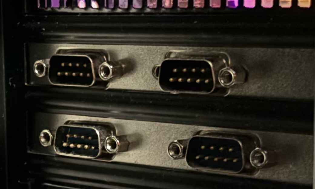
The CH340 family is a USB-UART interface that allows modern PCs to talk to a serial device using USB instead of the RS-232 port.
Compared to alternatives, such as FT232 and CP2012, CH340 is dirt-cheap. A CH340-based USB converter costs a few dollars, a CH340 chip costs less than half a dollar. I bought a CH340E chip for as low as 1.44RMB on Taobao, which is less than 0.3 CAD.
So, the low-cost is the advantage. What is the disadvantage? Some argue it is less reliable. However, I had never seen a failed CH340.
There is a nice article discussing the USB-UART interfaces: https://github.com/SpenceKonde/AVR-Guidance/blob/master/UPDI/jtag2updi.md
Plus, everyone using the USB-UART interface should know this story: One day FTDI decided to use the driver to F@ck up your chip if the driver detects a counterfeit chip. I do understand that the company is trying to protect their IP; however, as a consumer, I have no way to ensure whatever the vendor gives me is a genuine device, and I cannot allow the risk that a few dollars worse chip ruin my multi hundred dollar project during production without my consent. Furthermore, if the company can do some evil, they can do more. Yes, they cross the red line. So, I stay away from it; especially, there are alternatives that do the same job for less and no evil.
Because of its low cost, the CH340 is a go to option for a lot of low-cost devices, including the Arduino nano board.
CH340E
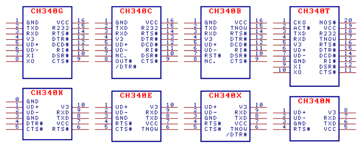
What makes CH340E special from other CH340 chips is its package:
- CH340E has only 10 pins. 2 for power (VCC and GND), 2 for USB connection (UD+ and UD-), 4 for UART (Tx, Rx, RTS, CTS), 1 status output (TNOW) and 1 external capacitor(V3).
- It comes with a built-in oscillator.
That means, it requires less external components. Especially, no external oscillator. All we need are:
- A USB connector. We can even use the PCB itself to make a USB-A male connector.
- The required external 0.1uF capacitor on its V3 pin.
- An optional capacitor between 5V power supply and GND.
I hate sourcing oscillators, they are not commonly used like resistors and capacitors; there are tons of different frequencies for different applications; they are big and ugly (cannot be small due to their physical nature). So, I like devices with an internal oscillator.
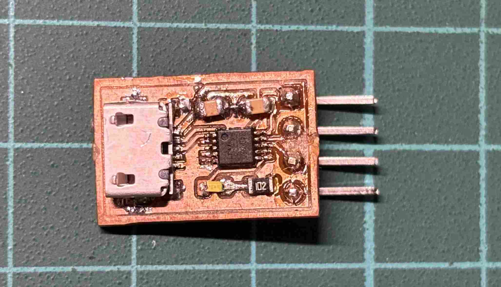
However, the CH340E only has the MSOP-10 package. The pin-to-pin distance is 0.5mm (0.3mm pad width, 0.2mm space between pads). This makes soldering difficult. Fabricating the PCB with CNC is even more difficult.
The CH340E Breakout Board
Circuit design
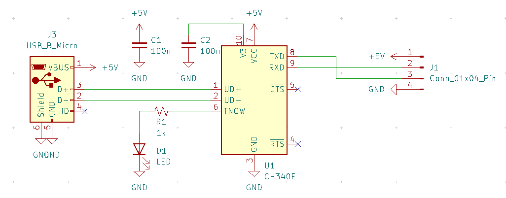
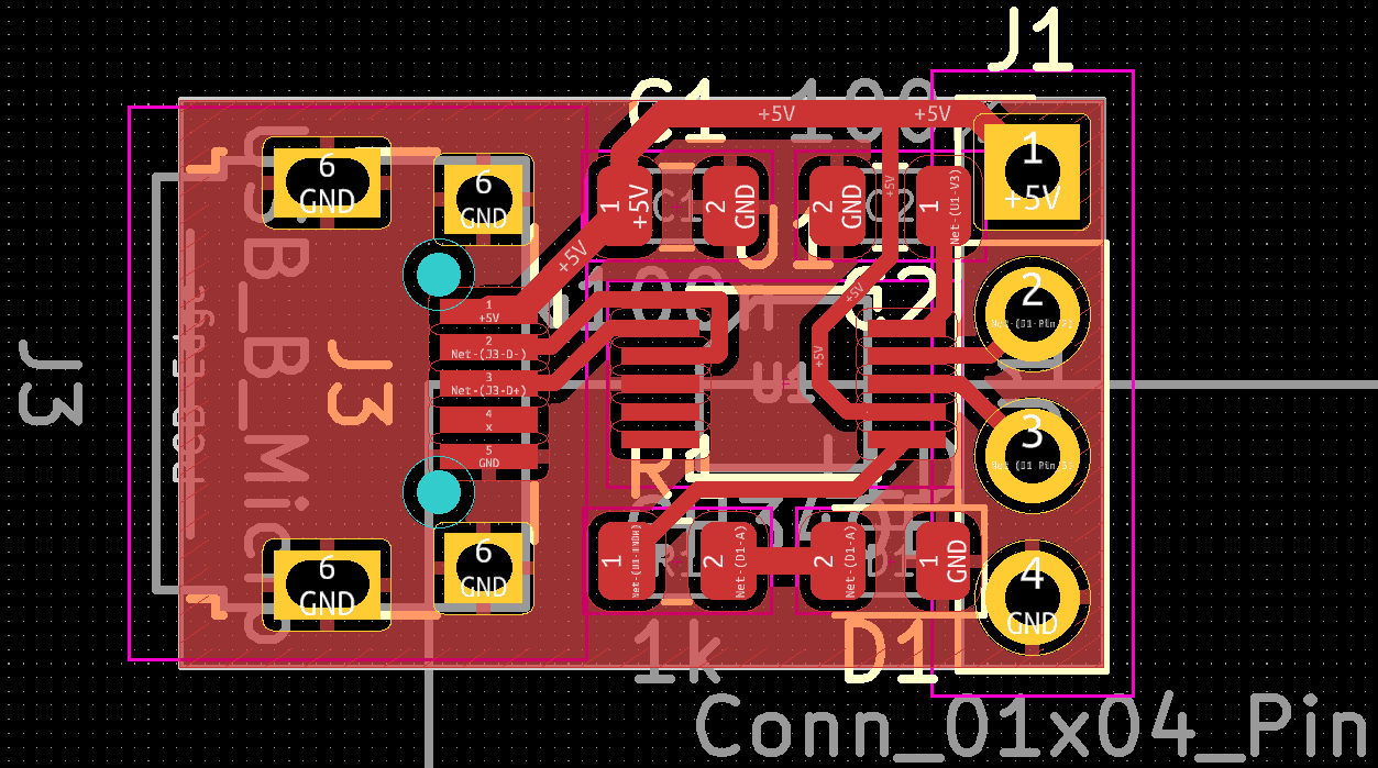
Following is a breakout board design based on the CH340E chip.
Here is the link to my KiCAD project for the breakout board.
In the center is the CH340E chip. On the top are two 0.1uF capacitors, one for 5V power filtering, one for V3. On the bottom left is a LED showing the status, the 1k ohms resistor is to limit the current through the LED.
On the left is a micro SUB connector. On the right is a 4 pin header for UART IO and 5V power supply for external devices.
The hardware flow control (RTS and CTS) is not used.
Benchtest
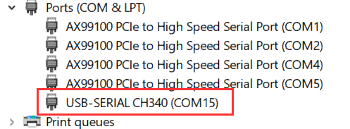
When connecting the breakout board to PC USB, the Windows device manager should successfully add a new COM device:
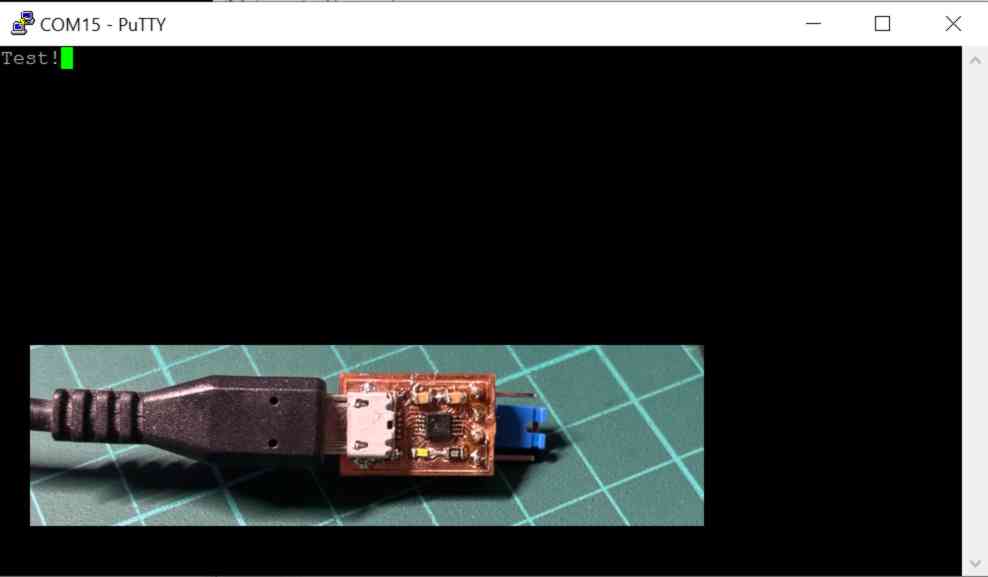
Use a jumper to short the Tx and Rx pins, we should see the data echo in the terminal: